Table of Contents
Advertisement
Quick Links
Advertisement
Table of Contents

Summary of Contents for Techno Trade TBOX MS
- Page 1 R emote T erminal U nit User’s Guide Technical specifications & cabling...
- Page 2 Disclaimer Every effort has been made to ensure the accuracy of the information in this guide. However, Techno Trade S.A. assumes no responsibility for the accuracy of the information. Product information is subject to change without notice. are registered trademark of Techno Trade s.a.
-
Page 3: Table Of Contents
5.3. Programs of ‘TWinSoft Suite’................. 29 6. S ..................30 TARTING 6.1. Wizard......................... 31 6.2. Communicating with TBox MS ................32 6.3. PC Communication Set up..................32 6.4. Testing communication..................34 6.5. Global reset of TBox MS..................35 6.6. LED « RUN »......................35 6.7. - Page 4 TWINSOFT - PROGRAMMING ..................39 7. I ....................40 NTRODUCTION 8. RTU ................... 41 PROPERTIES 8.1. General properties ....................42 8.2. Drivers......................... 43 8.3. Security ....................... 43 8.4. Info properties ..................... 44 8.5. Advanced ......................44 8.5.1. Startup ........................44 8.5.2.
- Page 5 11.3.1. About Redundancy....................81 11.4. NTP Server....................... 82 11.4.1. Time accuracy ......................82 11.5. TCP/IP Debugging .................... 83 ....................86 LARMS 12.1. Introduction ..................... 86 12.2. Digital Alarm Condition..................87 12.3. Analog Alarm Condition..................89 12.4. Recipients ......................91 12.5. Group of Recipients ..................93 12.6.
- Page 6 A.3. The Code (License) ....................184 A.4. The TWinSoft LITE ....................184 B. T RTU ................185 PPENDIX IME IN B.1. Time in TBox MS ....................185 B.2. Data logging ......................186 B.3. Special registers associated..................186 INDEX ........................... 188 Version: 1.06...
-
Page 7: Presentation
Version: 1.06... - Page 8 The unique ‘all in one’ includes the best of 3 Worlds: Telemetry Internet Automation Version: 1.06...
- Page 9 Overview of possibilities Consulting Programming: locally or process through HTML pages remotely Sending of Alarms Communication to a remote site Retrieving data and consulting the process remotely Retrieving data locally Version: 1.06...
-
Page 10: How To Use This Manual
1. How to use this manual? 1.1. What is in the manual? This manual represents the essential of documentation. It first introduces to the hardware concept including nice pictures ☺ Installation of Racks: chapter 3 Insertion of Cards: chapter 4 Then it brings you to the programming of using TWinSoft. -
Page 11: The Hardware Concept
2. The Hardware Concept is a Modular System. is built using Racks and Cards. Depending on your needs in communication(s) and in Inputs/Outputs, you select the elements required. 2.1. The Racks Racks are made in aluminium alodined, giving a very good electrical conductivity equipotentiality... -
Page 12: The Cards
2.2. The Cards Cards formed mounted aluminium enclosure which assures the best shielding against receiving and emitting noise (radio emission, electromagnetic interference, …) Bare aluminium inside enclosure edges assures a good contact of the ‘ground’ signal of the PCB between the Card and the Rack. -
Page 13: Hardware
Version: 1.06... -
Page 14: Installation Of The Rack
3. Installation of the Rack 3.1. Installation of the Rack on a DIN rail Each edge of the Rack is equipped with springs for DIN rail fixing Place the springs of the Rack under the bottom side of the DIN rail and pull-up the Rack Push the Rack against the DIN rail... -
Page 15: Installation Of The Rack In A 19'' Cabinet
3.2. Installation of the Rack in a 19’’ cabinet The Rack 15 slots can be mounted directly in the 19’’ cabinet. The height of the Rack is of 150 mm and adapted for a 4U cabinet (177.8 mm). You have then enough room for cabling the Cards. Special Sides must be fixed to the edges of the Rack Version: 1.06... -
Page 16: Insertion Of Cards In The Rack
4. Insertion of Cards in the Rack The Rack has a side UP and a side DOWN. When the direction of the Rack is correct, the logo A must be at the right side and the slot numbering readable. DOWN Example with the Rack 10 Each slot has a unique index number, starting at ‘0’... -
Page 17: Placing The Power Supply Card
4.2. Placing the Power Supply Card When using a power supply card, it is always placed at the first position in the Rack. It is important for thermal issue. Next to ‘Power Supply’ and ‘CPU’ cards, you can leave slots empty The CPU is placed at the second position. -
Page 18: Working Without Power Supply Card
4.3. Working without Power Supply Card If a power supply card is not required, the one from the CPU can be used. In this case the CPU is placed at the first position in the Rack Next to the ‘CPU’ card, you can leave slots empty If you intend to use later a ‘Power Supply’... -
Page 19: Hardware Vs. Software Address Of Cards
4.4. Hardware vs. Software Address of Cards Later in this document, we will see how to use the software TWinSoft, the tool for programming But as we mention slot index of the Rack, it is important to relate it to the corresponding software address. - Page 20 The corresponding TWinSoft configuration: The CPU has always address 0 The Power supply (when used) has always address 1 The I/O and Communication cards must de defined with the address corresponding to their position on the Rack. Version: 1.06...
- Page 21 With the following set of Cards on a Rack 5: Slot Address Card Description (hard) (soft) CPU 16 Modem PSTN 16 Digital Input 16 Digital Output empty The corresponding TWinSoft configuration: Version: 1.06...
-
Page 22: Powering
4.5. Powering Working with a Power supply, cabling of the Power supply: Power supply of CPU: connection when using a Example: Power Supply Card 230 Vac Power Supply (ref MS-PS230V) DO : Output for synchronization DI : Input for synchronization Battery + Ethernet : for communicating to other Racks / devices... - Page 23 Working without Power supply, cabling of the CPU: Example: -CPU16 with Ethernet (ref MS-CPU16E) Main voltage present +6 .. +30 VDC ‘Sync.’ output active DO : Output for synchronization DI : Input for synchronization ‘Sync.’ input active ON: 100 Mbps - OFF: 10 Mbps Ethernet : for programming, communicating to other Racks / ON: Link - Flash: Communication...
- Page 24 Version: 1.06...
-
Page 25: Twinsoft - Getting Started
Version: 1.06... -
Page 26: Installation Of Twinsoft
5. Installation of TWinSoft 5.1. System requirements • Hardware: Pentium or higher. • Memory: 16-MB minimum. We recommend 32 MB. • Hard Disk: 50 MB required plus the application files. • Display: VGA, SVGA with a minimum resolution of 640 x 480. We recommend 800 x 600. -
Page 27: Installation Of The Cd-Rom
5.2. Installation of the CD-ROM From the CD-ROM of TWinSoft Suite, when running the Setup, the following software’s are available • TWinSoft 9.00 TWinSoft is the software required for developing an application for the RTU. The basis for configuring a RTU application is explained in this manual. Installation of TWinSoft includes: WebForm Studio: HTML editor dedicated to RTU... - Page 28 • DreamWeaver Trial version • Report Studio for DreamWeaver Dreamweaver is a standard HTML editor. It can be used with the plug-in ‘Report Studio for Dreamweaver’ to develop standard HTML pages that do not use the ActiveX. • Acrobat Reader Software needed to read our documentation.
-
Page 29: Programs Of 'Twinsoft Suite
5.3. Programs of ‘TWinSoft Suite’ During installation of TWinSoft, a group of programs is created where TWinSoft can be started. Other programs and menus: • Accessories: group containing the utility ‘Password generator’ and ‘Reset User preferences’: reset of registry information to restore the default configuration of TWinSoft. -
Page 30: Starting Twinsoft
When you start TWinSoft the first time, or when you create a new document, I help you with some basic configurations. The use of TWinSoft is free, but sending of a program to TBox MS is protected. For more info about Licenses go to Appendix A. at the end of this manual. -
Page 31: Wizard
6.1. Wizard The ‘New Document Wizard’ helps you getting started with a new application by gathering information about your hardware and some basic configuration. Except for the ‘Type of RTU’, all those settings can be modified latter from the ‘RTU properties’. -
Page 32: Communicating With Tbox Ms
6.3. PC Communication Set up To communicate with the MS, you need to select a communication media on the PC. From the main menu of TWinSoft: Communication PC Setup: Example with a RS232 connection: default Baudrate of TBox MS : 9600,N Version: 1.06... - Page 33 Other possibilities of PC Setup: • Offline: this option avoid sampling • Local: you select a serial port of the PC (typically RS232). The Baudrate must fit with the port of you are connected to. If your PC is equipped with USB port, you can use a converter USB-RS232 •...
-
Page 34: Testing Communication
6.4. Testing communication Once you have selected the media on the PC, you can test the communication. From the main menu of TWinSoft: Communication RTU identification: Available information: - Name of the RTU - Type of Hardware - Version of Operating System - Status of the process - ModBus address of the Station - Subaddress of the Station... -
Page 35: Global Reset Of Tbox Ms
6.5. Global reset of TBox MS The Global Reset is used to set in a default, well-known configuration, in case it does not communicate anymore. This is very useful when you take a CPU from the stock and you have no idea how the port you want to communicate with is configured. -
Page 36: Saving And Sending A Program
6.7. Saving and Sending a Program Like any Windows program, TWinSoft creates ‘Documents’. One document corresponds to application. Each of them must be saved using the Windows standard. 6.7.1. Saving a document Possibilities for saving a document: • Use the icon of the main tool bar •... -
Page 37: Sending A Document
6.7.3. Sending a document In order to have the running with the program you have developed with TWinSoft, you have to send it. You can use any media to achieve it (RS232, modem, Ethernet, …). Possibilities for sending a program: •... - Page 38 Version: 1.06...
-
Page 39: Twinsoft - Programming
Version: 1.06... -
Page 40: Introduction
7. Introduction TWinSoft uses the standard look and feel of ‘Windows Explorer’, with at the left side a list of folders and at the right side the content of the folder selected. Each Folder consists in a list of items. For instance the list of Tags, or in the ‘Alarms’... -
Page 41: Rtu Properties
8. RTU properties Setting the properties of the has never been so easy thanks to a set of comprehensive dialog boxes, available from the main tool bar. RTU properties can be accessed easily by clicking this icon. The RTU properties are divided into: •... -
Page 42: General Properties
8.1. General properties RTU Type: The type of RTU you have selected with the Wizard (see chapter 6.1). It cannot be changed! Name: type a free name for the MS. It will be displayed when doing a ‘RTU identification’ and used by the supervisory T. Maximum 8 characters. -
Page 43: Drivers
OS version: when working Offline, it is the OS used to simulate the compilation. By default it is the OS version associated to version of TWinSoft. Telephone number: Configuration used by TWinSoft when it needs to dial Sizes: Number of records of Digital and Analog chronologies. The chronologies are the ‘on event’... -
Page 44: Info Properties
8.4. Info properties You can enter a version number, the name of the programmer and a description of your program. This information is not sent to 8.5. Advanced 8.5.1. Startup By Startup we mean: Reset of RTU (hardware or software) Sending of Program Under those conditions two mechanisms of the RTU can be customized. -
Page 45: Alarms
8.5.2. Alarms The advanced parameters of alarms concern the size of the stacks and customizing of e-mail and GSM message. Event stack: is a public stack where alarms are available with date, time, recipient, message, status, …. The Event stack can be displayed from the main menu: ‘Communication’ ‘Download’... - Page 46 SMTP subject: when receiving an e-mail from MS, the field ‘Subject’ contains the message or the title of the report (see Report Studio). It accepts any text and the following parameters: %station% : replaced by the name of the station (see General properties) %email% : replaced by the e-mail address of the RTU %time% : the time of the RTU when the e-mail was generated...
-
Page 47: Sampling Tables
8.5.3. Sampling Tables This menu gives access to the parameters for long period recording in Sampling tables. Sampling tables (See chapter 13.3: ‘ ’) Those configurations concern all sampling tables. Daily: When ‘daily’ is selected in sampling table, it is the time of the day the recording is executed. -
Page 48: Temperature
8.5.4. Temperature For Temperature analog input (PT100 or PT1000), you can define a unit: Celsius, Fahrenheit or Kelvin. The unit is the same for all inputs 8.5.5. Remote Tags Reset the device Trigger only if success When communicating ‘Master’ using ‘Remote Tags’, a Trigger is associated to the device the RTU communicate with (see Remote Tags). - Page 49 TCP Ports Numbers. Each TCP/IP service has its own unique TCP port. It provides a logical location for the delivery of TCP data. TCP Port number complies to a standard defined by the IANA to be sure everyone using a TCP service uses the same TCP ports according to protocols used.
-
Page 50: Environment Variables
8.5.7. Environment variables The environment variables are used when particular configuration might be needed in external software. Variable Value Description \path The path in which the station will be created when TViewPath importing data in T. The path is the relative path from the Project workspace of T. -
Page 51: Resources
9.1. The CPU-16 card When starting a new document, TWinSoft creates automatically the CPU card; the minimum for a TBox MS project ! The communication ports of the CPU with their associated configuration and the I/O of the CPU are available from the ‘Resources’:... -
Page 52: Communication Ports Of The Cpu
9.1.1. Communication ports of the CPU By selecting the Group 0 Communication ports the workspace, you access each port separately. enter configuration communication port, double click the port. Example with COM1 – RS232 Depending on the type of communication port (RS232. RS485, modem or Ethernet), different tabs are available: Parameters: general parameters (local or modem, Baudrate, Protocol). -
Page 53: Adding Cards
9.2. Adding Cards All cards other than the CPU must be added in the ‘Resources’ folder: I/O cards as well as communication cards. Starting a new document, the only card available is the CPU. You will add all cards corresponding to your hardware into this list. - Page 54 Example: Adding a Power Supply card: Id number of the cards in TWinSoft vs. Slot in the Rack: Type of Card Slot used in the Rack Address in TWinSoft Power Supply (if used) Always 0 0: when used without Power Supply Always 0 1: when used with a Power supply or alone in prevision of using a Power Supply...
-
Page 55: Adding An I/O Card
9.2.1. Adding an I/O card The Hardware is represented in TWinSoft with a hierarchy of 3 levels: CARD : CPU card, 16 DI card, COMBO card, Modem card, … GROUP : when there are several types of I/O on a Card, they are separated into Groups: group of DI, group of DO, group of AI, …... -
Page 56: Adding A 'Modem' Card
9.2.2. Adding a ‘Modem’ Card A modem card (PSTN or GSM) is composed of a modem and a serial port (RS232 or RS485). Technical specifications are available at the end of the manual. Once created, ‘modem’ provides one Group 0 with communication ports. -
Page 57: Adding A 'Gsm / Gprs' Card
Outside line prefix: if is placed behind a telephone switch (PABX), it is the number to get the outside line. This prefix will be applied automatically each time dials out. Default Initialization and prefix can be modified from the file ‘ModemProfiles.xml’. - Page 58 GSM-data settings Initialization: should not be changed PIN Code: If the SIM card you have inserted uses a PIN code, type it at the place of the letter n. Example: with the PIN code 4896, you should have in the field: AT+CPIN=“4896” If the SIM card you have does not require a PIN code, you can leave the field as it is or erase it.
- Page 59 GPRS settings Once you have declared a MS-GSM card, you have to activate the GPRS mode. You have to choose either ‘GSM-Data’ mode OR ‘GPRS’ mode. It is not possible to use the modem in both modes. When selecting GPRS, TWinSoft automatically adapts...
- Page 60 Communication Variables dedicated to GPRS Some communication variables allow manual handling of GPRS and give information on the status. Digital Communication Variable GPRS: Handles the GPRS connection. COMx.GPRSCon Working in manual connection, writing ‘1’ forces a connection; writing ‘0’ forces a disconnection. When working with automatic connection, if you reset this variable the connection will stop, but after maximum 5 minutes, it will be automatically restarted.
- Page 61 About sending alarms with GPRS With GPRS, you are able to send e-mail or files using FTP. You create recipient(s) associated to the SMTP or FTP server you have associated to the GSM/GPRS. Working with a manual connection, first the RTU establishes the connection and sends the mail and/or files.
-
Page 62: Communication Variables
9.3. Communication Variables Communication variables are dedicated registers to status of the communication. It is very useful for controlling the connection and the access level authority. Those variables are divided into 2 tabs, the Digital Communication Variables (DCV) and the Analog Communication Variables (ACV). -
Page 63: Analog Communication Variable
Communication: Reading ‘1’ indicates the port is transmitting. At COMx.ModBusResp each transmission, SET this register. To check is transmitting, you RESET this register and test whether it is SET again (using Ladder or BASIC) 9.3.2. Analog Communication Variable According to its function a Communication variable is Read/Write or Read only. -
Page 64: System Variables
9.4. System variables The system variables have pre-defined functions. They are very useful to check or to act on features of They are divided into ‘Digital’ and ‘Analog’. 9.4.1. Digital System Variables According to its function a register is Read/Write or Read only. In the following table, the column R/W indicates: : Read only. - Page 65 Index Name Description Flag analog chronology: can be associated to any analog chronology DisCra configuration to inhibit recording. When at value ‘1’, inhibits recording in Database. (Not used) DisSam Flag sending alarm: can be associated to any Alarm condition. When DisAla at value ‘1’, inhibits the sending of alarm.
-
Page 66: Analog System Variables
9.4.2. Analog System Variables According to its function a variable is Read/Write or Read only. In the following table, the column R/W indicates: : Read only. : Writable. Index Name Description Time: Second in Second Time: Minute in Minute Time: Hour in Hours Time: Day of the month in Date... -
Page 67: Timers & Counters
Index Name Description Operating System build: build number of the OS running in OsBuil Loader version: Loader version running in LoaVer Loader build: build number of the loader running in LoaBui Selection of the port for TCP debugging (see chapter 11.5) PortIdLog Contains internal codes used for TCP debugging EventLog... -
Page 68: Tags
10. Tags A Tag is essential for any programming • An alarm is conditioned from a Tag. • The Datalogging mechanism records values of Tags. • BASIC/Ladder programming executes a process by handling Tags. • … Any variable of the that you want to use in any configuration, you have to declare it as a Tag. -
Page 69: Physical I/O
10.1. Physical I/O The physical I/O’s are the signals available on I/O cards. They can be easily accessed from ‘The Resources’ the ‘Resources’ (see chapter 9: To create a Tag of a variable from the Resources: select it into the list and double click it change its name and description click <OK>... -
Page 70: Internal Variables (Registers)
10.2. Internal Variables (Registers) An internal variable (also know as Register) is an addressable location of the memory. It is used as flag, as temporary value, to make a calculation, … There are 2 types of internal variables: Digital (DIV) Boolean register with possible values: 0 or 1. - Page 71 The Definition menu pops up: You type a Tag Name, a Comment and select as Type: ‘Internal Variable’ The initial value is the value the Tag will have at the start up of ‘None If you select ’ the value is maintained at start up. ModBus Address is discussed in chapter 10.3 Version: 1.06...
-
Page 72: Analog Internal Variable
10.2.2. Analog Internal Variable To create an Analog Internal Variable (also known as Register), from the list of Tags, click Add a Tag’ ‘ ‘Analog’ Select The Definition menu pops up: Example with a ’32 bits – Unsigned’ internal variable Version: 1.06... - Page 73 You type a Tag Name, a Comment and select as Type: ‘Internal Register’ For each Analog Register, the formats available are: o 8 bits (Signed or Unsigned) o 16 bits (Signed or Unsigned) o 32 bits (Signed or Unsigned) o Float (IEEE 754) By default, TWinSoft creates Analog Internal Variable in format ‘Float’.
-
Page 74: Modbus Address
10.3. ModBus address The ModBus address is the link to the outside world. When equipment must sample Tags in MS, it uses its ModBus addresses; like T, SCADA or TWinSoft. Each Tag has a unique ModBus address. By default TWinSoft proposes a ModBus address. You can change it if you want. -
Page 75: Tags - Presentation / Write
Report: file edited with ‘Report Studio’ and used for instance as text body when sending e-mail. (Start ‘Report Studio’ from ‘Windows’ and the group of Programs of Techno Trade or from the ‘Project Workspace’ and the list of ‘Web and Report files’) WebForm: file edited with ‘WebForm studio’. -
Page 76: Ip Parameters
11. IP Parameters IP parameters consist in the global configuration for: connecting to an ISP sending files (FTP) sending e-mail (SMTP) Time synchronization (NTP) Concerning IP configuration of Ethernet card, refer to the corresponding card in the ‘Resources’. Concerning IP configuration for incoming calls (WebServer), see advanced RTU properties TCP/IP All IP parameters... -
Page 77: Isp Configuration
11.1. ISP configuration ISP stands for Internet Service Provider. An ISP represents the entrance to Internet. It is the company you call to access an Internet service, like sending e-mail or files (FTP). Some among the most well-known: Hotmail, AT&T, Scarlet, … When you want to send e-mail or send files to a FTP site, you subscribe an account to an ISP. - Page 78 DNS: A DNS converts names in IP address. It is needed by the TB MS to establish the connection with the Mail Provider in case the e-mail Server is indicated in 'text' and not with an IP address. More and more ISP support dynamic DNS, they provide the DNS addresses when connecting.
-
Page 79: Ftp Host
11.2. FTP Host FTP stands for File Transfer Protocol. When subscribing an account to an ISP, usually you have some Mbytes to your disposal for sending files. The FTP host represents the target when sending files. The directory where the files are sent is defined in the Recipient (see chapter 11). -
Page 80: Smtp Server
11.3. SMTP Server SMTP stands for Simple Mail Transfer Protocol. It is usually the main reason for subscribing an account to an ISP, for sending and reading e-mail. Concerning e-mail, is able to send e-mail and not to read e-mail. That explains why we speak only of SMTP and not POP3 (used for reading e-mail) The SMTP Server represents the mail server used for sending e-mail (typically the one of the ISP where we have subscribed an account). -
Page 81: About Redundancy
The Server requires Authentication: Depending on your ISP and on the way you send e-mail, authentication might be needed to send e-mail. Usually, when you have subscribed the e-mail account at your ISP it is not required. To be sure, if you have created this account on a PC, check its configuration otherwise contact your ISP. -
Page 82: Ntp Server
11.4. NTP Server NTP stands for Network Time Protocol, an Internet standard protocol (built on top of TCP/IP) that assures accurate synchronization to the millisecond. The NTP Server represents a server dedicated to time synchronization. First, connects to Internet (through an ISP connection) and then to the NTP Server. -
Page 83: Tcp/Ip Debugging
11.5. TCP/IP Debugging This feature is very convenient to trace problems when sending e-mails and/or files (with FTP). It informs on the different steps of the connection: Login to the ISP, obtain of DNS, Smtp communication, … It is based on 3 ‘System variables’: TcpIpLog, PortIdLog and EventLog Procedure 1. - Page 84 4. Example of TraceLog when sending e-mail works fine: Closing connection SMTP (e-mail) dialog Obtain DNS from ISP Agreement on options supported Authentication (PAP or CHAP) Agreement on options supported Modem connected uses the ‘Analog Chronologies’ to store debugging data: 1.
- Page 85 5. Example of TraceLog when sending Files (FTP) works fine: Closing connection FTP (sending files) dialog Obtain DNS from ISP Agreement on options supported Authentication (PAP or CHAP) Agreement on options supported Modem connected Version: 1.06...
-
Page 86: Alarms
(see from ‘Windows’ the group of programs of ‘Techno Trade’). TView , the supervisory software can then be used to collect data from a mail box or a FTP site. -
Page 87: Digital Alarm Condition
To access the definition of Conditions, click the folder ‘Alarms’ in the Project workspace and select ‘Conditions’. According to the Tag you select, you define a digital alarm condition or an analog alarm condition. 12.2. Digital Alarm Condition Tagname: The Tag selected to generate the alarm. Type: The edge on which the alarm is going to be started (rising, falling or both). - Page 88 Handling: The handling option allows blocking each alarm condition, manually or automatically. Enabled: alarm condition always active. Disabled: alarm condition always de-activated. PowerF: alarm condition disabled when there is a main power failure. DisAla: alarm condition de-activated when the system variable ‘DisAla’ is at 1. Severity: Each alarm can be assigned a level of severity: Low, Normal or High.
-
Page 89: Analog Alarm Condition
12.3. Analog Alarm Condition Tagname: The Tag selected to generate the alarm. Type: Maximum or Minimum. The threshold for which the alarm will be started. If the value of the analog Tag passes under (minimum) or over (maximum) this threshold, the alarm is started. - Page 90 Message or Report: text or file associated to the alarm. Depending on the recipient associated, it is the SMS sent to a GSM, or the message/report sent as e-mail or the text printed, or the file sent by FTP … It also appears in the table of alarms, to distinguish them (see chapter 12.7).
-
Page 91: Recipients
12.4. Recipients To access the definition of Recipients, click the folder ‘Alarms’ in the Project workspace and select ‘Recipients’. The types of recipients supported are: Internal: the alarm is saved in the stack of events and no call is generated. It can be used to memorize a particular event without generating an alarm or to test an alarm condition. - Page 92 Printer: sending of message(s) or report to a local printer. SMTP Server E-mail: If you have subscribed an e-mail account (see chapter 11.3. is able to send an e-mail. You only have to specify the e-mail address of the recipient. Sending of e-mail supports Redundancy.
-
Page 93: Group Of Recipients
12.5. Group of Recipients A group of recipients is composed of several recipients, which can be of different types (SMS, e-mail, …). You can declare several groups. Then previous to creating groups of recipients, you have to create the recipients (see above). -
Page 94: Messages
12.6. Messages To access the definition of Alarm messages, click the folder 'Alarms' in the Project workspace and select 'Messages'. Message number : indicates the index of message corresponding to its position in the list of messages. Type a message of maximum 120 characters. This message is user specific: - If it is for a Digital Pager, it will consist only of numbers. -
Page 95: Alarms Table
yyyyy: represents the ModBus address of the variable. It can be checked from the list ModBus address of Tags (see chapter 10.3. Examples of message Messages sent ANA0=~B64~too high ANA0=234 too high Register AIR0=~W20480~ Register AIR0=24563 Motor is ~o32~ Motor is OFF 12.7. -
Page 96: Columns Description
12.7.1. Columns description Start Timestamp: Date and Time when the alarm condition appears (‘Start’ condition) Message: Message (or name of the file) associate with the alarm. System events appear between brackets. Start: Acknowledgement status of the ‘Start’ condition. The possibilities are: Not ack.: the alarm is still in process. -
Page 97: Datalogging
13. Datalogging 13.1. Introduction Datalogging relies on the database inside MS. Datalogging allows memorizing events of your process, in order to visualize its history. contains 72 Kbytes of memory for recording events; the latter is what we call the database of There are two categories of databases: The Chronologies Chronologies are 'On event' recordings, by mean of changes in Tags. - Page 98 Recording into chronologies happens ‘on event’, but the minimum resolution in timestamp is the second. The sampling for Tags used in Ladder/Basic depends on the cycle of the process. For other Tags, sampling is executed every second. In case of recording using Ladder/BASIC, with several records during the same second, the data is sorted with the chronological order (latest at the top) but with the same second.
-
Page 99: The Chronologies
13.2. The chronologies 13.2.1. Digital chronologies Example of an entry in Digital chronology: Recording of the starting and stopping of a ‘Pump_1’. Edges: Recording on positive and (or) negative edge. Handling: Enabled: always recorded. Disabled: never recorded. PowerF: recording disabled in case of main power failure. DisCRD: recording disabled when the system variable ‘DisCRD’... -
Page 100: The Sampling Tables
13.3. The sampling tables Type: is able to execute calculations on a minimum time-base of 1 second. The result of the calculation is written in the sampling table after the period selected (see next). This value can be: Minimum : minimum value during the period. -
Page 101: Remote Tags
14. Remote Tags 14.1. Introduction Remote Tags allow exchanging information between two or more ModBus stations via any communication ports. Typically, it is a connected to another MS, either local (through RS485 or Ethernet) or remote, by modem. One often speaks of 'Master Network' because it is a Master/Slave communication: the Master executes reading and writing in slave(s). -
Page 102: Creating A Remote Device
Previous to create Remote Tags you have to create the equipment you are going to communicate with. 14.2. Creating a Remote Device From the Project Workspace, select ‘Resources’ ‘I/O’. Click ‘I/O’ and in the list of I/O, click ‘Add an I/O card’. Remote TBox: a (CPU-3) ModBus device: a... -
Page 103: Creating Remote Tag
14.3. Creating Remote Tag Example: reading of 8 ‘floating’ variables in TBox#2 at address 32 Tag: Select an existing Tag by clicking the button. Be sure you select a Tag of the same type of the address you want to access in the ‘Slave’ (Byte, Word or Float). If the Tag does not exist, you can create it after having clicked the button. - Page 104 External Source. All the following parameters concern the Slave station: Device: select an existing external device from the ‘Resources’. You can create one clicking the button Type: select the type of the external variable. According to the external source, the choices are: With External source ‘ModBus device’...
-
Page 105: Remote Tags Through Modem
14.4. Remote Tags through modem With a remote device accessed by modem, the connection must be first established using an Alarm. The sequence is the following: • Create an Alarm Recipient of type ‘ModBus - Master’, with the telephone number of the remote device. -
Page 106: Periodic Events
15. Periodic Events The idea is to give the possibility to execute events, such as Remote Tags, alarm calls, datalogging, process, etc ... periodically, independently of any other condition. A periodic event could be compared to an automatic timer. A digital Tag is used to trigger the event(s). It is SET by the Operating System of when the task(s) must be carried out and RESET by the OS when the task(s) have been launched. - Page 107 Example of a ‘daily event’: The Tag ‘event1’ (a DIV) will be automatically SET every 30 minutes, at each xx:15:00 and xx:45:00. The action(s) configured with ‘Event1’ will be generated every 30 minutes. Example of a ‘weekly event’: The Tag ‘event2’ (a DIV) will be automatically SET every day at 6:00:00 AM. The action(s) configured with ‘Event2’...
-
Page 108: High Speed Tags
16. High Speed Tags The high-speed Tags were designed to receive pulses on digital inputs, with handling independent from the process cycle. If the delay between two successive pulses is smaller than the cycle time of the process, it will not be possible, for instance, to make counting from the program. Then you can use the High Speed Tags. -
Page 109: Processor Time For Executing High Speed Tag
If the weight is smaller than 1 (0.1, 0.2, …) be sure the Target Tag is of type ‘Float’. Example: counting water consumption - you receive pulses each 10 liters - you want to count each 100 liters - you want to display the result in m³ Dividor: 10 Weight: 0.1 16.1. -
Page 110: Access Security
17. Access security This (optional) access security of the prevents non-authorized persons from accessing the RTU. If the Access security option is activated, each port of the can be independently protected. The standard protection concerns ‘ModBus’ protocol, on serial and modem ports. A protection on Ethernet connection is not available yet. -
Page 111: Rtu Configuration
17.1. RTU configuration The configuration of security of is available from the ‘RTU properties’: there is a general activation of the protection. for each serial or modem port, you activate the protection. 17.1.1. RTU Properties From the RTU properties tab ‘Security’, you activate the general access security feature. -
Page 112: Password Utility
When installing a password-creation program named PASSWORD is installed in the same directory as TWinSoft. It can be started from the 'Start' button of Windows and is located in the group of programs “Techno Trade” “Accessories” created while installing TWinSoft. -
Page 113: Login/Logout
Access level Three access levels are available: Level 1: Surveillance mode or VISUALIZATION MODE. The operator can view all values (local or remote), but can not execute any command. Level 2: COMMAND MODE, the operator can view all the values and execute commands (locally or remotely). -
Page 114: With Internet Explorer
If 'Save password' is checked and TWinSoft is connected to a protected port: when TWinSoft starts, it uses the access level corresponding to the password saved (see the status line). If it is not checked and TWinSoft is connected to a protected port: TWinSoft starts in 'Read only' mode. -
Page 115: Deactivating Protection
17.4. Deactivating protection There are two methods of deactivating access protection: Global reset (see chapter 6.5) The first method is by performing a global reset, which must be done on site. When the program has stopped, the local port is no longer protected. If a card ‘modem’... - Page 116 Version: 1.06...
-
Page 117: Technical Specifications - Cabling
Version: 1.06... -
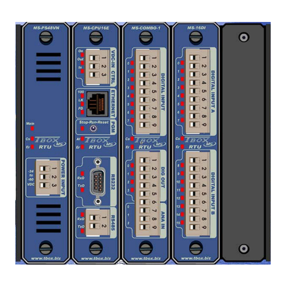
Page 118: Racks & Cards
18. Racks & Cards References: 18.1. Racks MS-RACK5 MS-RACK10 MS-RACK15 Racks used as base for the Cards. Exist in 4 versions: Rack 5 slots Rack 10 slots Rack 15 slots Rack 20 slots E C H N I C A L P E C I F I C A T I O N S General Speed... -
Page 119: Power Supplies
References: 18.2. Power Supplies MS-PS230V MS-PSDCN MS-PS48VN 230 V -48 …+ 24 VDC - 48 VDC Version: 1.06... - Page 120 E C H N I C A L P E C I F I C A T I O N S 230 VAC Input Voltage input: - AC 85..265 Vac (47..440 hz) - DC 90..375 Vdc Power Input Power at I out max. Maximum: 20 W Input Power in over load or short-circuit Maximum: 50 W...
- Page 121 24 VDC Input Voltage input: - either +24V +8 .. +30 VCC - either -48V -60 .. -24 VCC Power Input power at maximum current Maximum: tbd Input power with short-circuit (or over load) Maximum: tbd Efficiency Minimum: tbd Output power Maximum: 15 W Output Battery charger:...
- Page 122 - 48 VDC Voltage / Current V in -60 to –24 VDC Output current on the BUS (3.3V) Consumption 10 mA Power Input Power at I out=2 A Maximum: 12 W Input Power in over load or short-circuit Maximum: 65 W Efficiency Minimum: 60% at 2 A Protection...
- Page 123 A B L I N G For electrical security reason, you have to manipulate connectors with power switched OFF. 230 Vac Power supply Description: Connector: POWER UNIT Power Supply 230 VAC 7.68 CREW CONNECTOR 230 Vac - L earth 230 Vac - N Description: Connector: POWER UNIT Power Supply 110 VAC...
- Page 124 For electrical security reason, you have to manipulate connectors with power switched OFF. 24 Vdc Power supply Description: Connector: POWER UNIT Power Supply 24 VDC Screw connector (4 x 5.08 mm) +8 .. +30 VCC +24V -48V Terre Earth Description: Connector: POWER UNIT Power Supply - 48 VDC Screw connector (4 x 5.08 mm)
-
Page 125: Bits
References: 18.3. CPU-16 bits MS-CPU16 Hardware on all models: Power supply input Button for selection of the mode of working RS232 RS485 I/O for synchronization Internal temperature measurement Input voltage measurement Ethernet E C H N I C A L P E C I F I C A T I O N S General Processor... - Page 126 Internal Battery (see schema following) Voltage Backup of Clock and RAM (datalogging) Lifetime CPU under voltage: 10 years CPU stopped and plugged on the Rack: - Typical 265 days - Minimum: 29 days WARNING: After this time, the battery must be replaced to maintain the clock and datalogging.
- Page 127 Input/Output Synchronization I/O Multipoint connection between CPU Use: synchronize actions on several CPU in the same cabinet Synchronization Input Use: to receive ‘Synchronization Output’ from other CPU Vin: 0 5.5 V Protection: Over voltage: max. 33 V Inversion: max. 29 V Synchronization Output Use: to connect to ‘Synchronization Input’...
-
Page 128: Lithium Battery
Battery and MultiMedia card implementation: RS 485 RS 232 POWER Lithium MultiMedia battery Card Battery Jumper 18.3.1. Lithium Battery The CPU is equipped with a Lithium battery (3 V). This battery is used to maintain the clock and datalogging when the CPU is out of power. This battery is in use when: the CPU is placed on a Rack the CPU has been powered once... -
Page 129: Multimedia Card
18.3.2. MultiMedia card To use the MultiMedia Card, remove the CPU from the Rack and insert the MultiMedia cards in the appropriate socket. The MultiMedia card can be used to initialize For the moment, the only initialization available concerns the IP configuration of the Ethernet port. -
Page 130: Power Supply
A B L I N G Power Supply Description: Connector: VDC-IN CTRL Power Supply Screw connector (4 x 5.08 mm) +6 .. +30 VDC V in When using a Power Supply card (see previous), you do not cable Power supply of the DI - DO Description: Connector: VDC-IN CTRL... - Page 131 RS 485 Description: Connector: RS485 RS485 communication Screw connector (3 x 5.08 mm) Cabling several CPU together: A to A B to B Gnd to Gnd About RS485 cabling: 1. Use a twisted pair for signal A and B. 2. RS 485 is not isolated. If cabling equipment in different building (different Earth), you have to use ACC-RS485 (see your local distributor) 3.
- Page 132 RS 232 Description: Connector: RS232 Pin out: RS232 9 Pin Sub D RxD (input) TxD (output) RTS (Output) CTS (input) Cabling to a PC - COM1 PC - DB 9 RxD 2 2 RxD TxD 3 3 TxD GND 5 5 GND RTS 7 7 RTS...
- Page 133 Ethernet Description: Connector: RJ45 Pin out: Ethernet not used not used not used not used Cross over cabling To cable directly to a PC, without HUB or Switch, you can use a X-over cable: – COM4 PC – Ethernet RJ45 RJ45 Tx + 1 1 Tx +...
-
Page 134: I/O Simulation
References: 18.4. I/O Simulation MS-IO-SIMUL 8 digital inputs: available with switches 8 digital outputs: available with LEDs (ON/OFF) 4 analog inputs: available with potentiometer 4 analog outputs: available with LEDs (brightness variation) MS-IO-SIMUL is the ideal card for making test and demonstrate Version: 1.06... -
Page 135: 16 X Digital Inputs
References: 18.5. 16 x digital Inputs MS-16DI 2 groups of 8 digital inputs isolation by group of 8 inputs E C H N I C A L P E C I F I C A T I O N S General Quantity 16 inputs... - Page 136 16 x Digital Inputs (next) Isolation 2 groups isolated Isolation by group of 8 inputs From the Ground Isolation from the CPU ground and the earth Level of isolation 1500 Vrms - between group - between Inputs and ground - between Inputs and earth Protection Test Automatic test of the access of the card by the CPU...
- Page 137 16 x Digital Inputs (next) A B L I N G Description: Connector: Pin Out: Cabling of inputs Screw connector +12 .. 60 VDC Input 0 Input 1 Input 2 Input 3 Group A Input 4 Input 5 Input 6 Input 7 +12 ..
- Page 138 16 x Digital Inputs (next) Cabling to Dry contact Input x Cabling to NPN transistor Cabling to PNP transistor (or OPTO) 1 k (12 VDC) 10 k (24 VDC) Input x Input x Cabling to Voltage sensor Sensor Input x Version: 1.06...
-
Page 139: 16 X Digital Outputs
References: 18.6. 16 x digital Outputs MS-16DO 2 groups of 8 digital outputs isolation by group of 8 outputs E C H N I C A L P E C I F I C A T I O N S General Quantity 16 outputs... - Page 140 16 x Digital Outputs (next) Isolation 2 groups isolated Isolation by group of 8 outputs From the Ground Isolation from the CPU ground and the earth Level of isolation 1500 Vrms - between group - between Outputs and ground - between Outputs and earth Protection Test Automatic test of the access of the card by the CPU...
- Page 141 16 x Digital Outputs (next) A B L I N G Description: Connector: Pin Out: Cabling of outputs Screw connector +6 .. 60 VDC Output 0 Output 1 Output 2 Output 3 Group A Output 4 Output 5 Output 6 Output 7 +6 ..
-
Page 142: 16 X Digital Inputs/Outputs
References: 18.7. 16 x digital Inputs/Outputs MS-16DI0 2 groups of 8 digital inputs/outputs isolation by group of 8 inputs/outputs each channel can be cabled as an input or an output Version: 1.06... - Page 143 16 x Digital Inputs/Outputs (next) E C H N I C A L P E C I F I C A T I O N S General Quantity 16 channels. Each can be cabled as Input or Output Replacement Hot insertable/removable. There is no risk to damage hardware, but a reset is required.
- Page 144 16 x Digital Inputs/Outputs (next) Inputs Voltage at input Typical 24 VDC Maximum for a LOW level 5 VDC Minimum for a HIGH level 11 VDC Maximum 60 VDC Compatibility with type 1 and 2 of IEC61131-2 Current Maximum at the input 2.0 mA at 30 VDC 4.5 mA at 60 VDC Resistance...
- Page 145 16 x Digital Inputs/Outputs (next) A B L I N G N P U T S Description: Connector: Pin Out: Cabling of inputs Screw connector +12 .. 60 VDC Input 0 Input 1 Input 2 Input 3 Group A Input 4 Input 5 Input 6 Input 7...
- Page 146 16 x Digital Inputs/Outputs (next) Cabling to Dry contact Input x Cabling to NPN transistor Cabling to PNP transistor (or OPTO) 1 k (12 VDC) 10 k (24 VDC) Input x Input x Cabling to Voltage sensor Sensor Input x Cabling both Input and Output Input/Output x This type of cabling can be used in 2 cases:...
- Page 147 16 x Digital Inputs/Outputs (next) A B L I N G U T P U T S Description: Connector: Pin Out: Cabling of outputs Screw connector +12 .. 60 VDC Output 0 Output 1 Output 2 Output 3 Group A Output 4 Output 5 Output 6...
-
Page 148: Combo (Multiple I/O)
References: 18.8. COMBO (Multiple I/O) MS-COMBO-1 1 group isolated of 8 digital inputs 1 group isolated of 4 digital outputs 1 group non isolated of 3 analog inputs Version: 1.06... - Page 149 COMBO (next) E C H N I C A L P E C I F I C A T I O N S General Quantity 8 digital inputs 4 digital outputs 3 analog inputs (14 bits) Replacement Hot insertable/removable. There is no risk to damage hardware, but a reset is required.
- Page 150 COMBO (next) 8 x Digital Inputs Voltage at input Typical 24 VDC Maximum for a LOW level 5 VDC Minimum for a HIGH level 11 VDC Maximum 60 VDC Compatibility with type 1 and 2 of IEC61131-2 Current Maximum at the input 2.0 mA at 30 VDC 4.5 mA at 60 VDC Resistance...
- Page 151 COMBO (next) 3 x Analog Inputs General Model 4..20 mA ; passive Mode 4..20 mA Range Typical: 4 mA to 24 mA Minimum: 4 mA to 22 mA Impedance Minimum: 21 ohms Typical: 23.9 ohms Maximum: 26.4 ohms Value for LSB Typical: 2.935 µA Digital Input Validity input associated to...
- Page 152 COMBO (next) – D A B L I N G I G I T A L N P U T S Description: Connector: Pin Out: Cabling of inputs Screw connector +12 .. 60 VDC Input 0 Input 1 Input 2 Input 3 Group A Input 4...
- Page 153 COMBO (next) – D A B L I N G I G I T A L U T P U T S Description: Connector: Pin Out: Cabling of Outputs Screw connector +12 .. 60 VDC Output 0 Output 1 Group B Output 2 Output 3 Version: 1.06...
- Page 154 COMBO (next) – A A B L I N G N A L O G N P U T S Description: Connector: Pin Out: Cabling of 4..20ma sensors Screw connector Group C Input 0 4..20 mA Input 1 4..20 mA 4..20 mA Input 2 Gnd is not isolated from the Gnd...
-
Page 155: Analog Inputs
References: 18.9. 8 x Analog Inputs MS-8 AIVC 1 group of 8 analog inputs 8 x -10..+10V; -20..+20mA 2 x Pt100, Pt1000 instead of 2 linear inputs Version: 1.06... - Page 156 8 ANAIN (next) E C H N I C A L P E C I F I C A T I O N S General Quantity 8 analog inputs Signals: - for the 8 inputs Choice between: –10..+10V OR –20..+20mA (see cabling) - for 2 of the 8 inputs Supplementary choice between Pt100 OR Pt1000 2 wires (see cabling) No hardware or software configuration is required...
- Page 157 8 ANAIN (next) – A A B L I N G N A L O G N P U T S Description: Connector: Pin Out: Cabling of 4..20ma sensors Screw connector Input 0 - Temperature Input 0 - Voltage Input 0 - Current Group A Input 1 - Voltage Input 1 - Current...
-
Page 158: Temperature Inputs
References: 18.10. 8 x Temperature Inputs MS-8 RTD Not available yet 2 groups of 8 analog inputs Temperature inputs : Pt100, Pt1000, Ni100, Ni1000 2 or 3 wires Version: 1.06... - Page 159 8 RTD (next) E C H N I C A L P E C I F I C A T I O N S General Quantity 8 temperature inputs Signals Choice between Pt100, Pt1000, Ni100, Ni1000 2 wires or 3 wires The selection of the probe is done by the cabling used.
- Page 160 8 RTD (next) – A A B L I N G N A L O G N P U T S Description: Description: Cabling Probes 2 Wires Cabling Probes 3 Wires Group A Group B There is no isolation. It means Gnd are connected together and the Earth.
-
Page 161: Analog Outputs
References: 18.11. 4 x Analog Outputs MS-4 AOVC 4 analog output isolated one by one each output: 4..20 ma or –10V..+10V Version: 1.06... - Page 162 4 ANAOUT (next) E C H N I C A L P E C I F I C A T I O N S General Quantity 4 analog outputs Signals - for each output Choice between 4..20ma OR –10V..+10V The selection of the signal is done by the cabling used. No hardware or software configuration is required ADC converter 12 bits, bipolar...
- Page 163 4 ANAOUT (next) – A A B L I N G N A L O G U T P U T S Description: Connector: Pin Out: Cabling to 4..20ma OR Screw connector -10V..+10V actuators No connection Output 0 : 4..20mA (+) Output 0 : 4..20mA (-) Group A Output 0 : -10V..+10V (+)
- Page 164 Cabling to ‘Current’ actuator OUT+ Actuator 24 V OUT- Feedback Cabling to ‘Voltage’ actuator OUT+ Actuator OUT- Version: 1.06...
-
Page 165: Relay Outputs
References: 18.12. 8 x Relay Outputs MS-RELAY 8 relay outputs isolated one by one Version: 1.06... - Page 166 8 Relay Outputs (next) E C H N I C A L P E C I F I C A T I O N S General Quantity 8 outputs Consumption Replacement Hot insertable/removable. There is no risk to damage hardware, but a reset is required.
- Page 167 8 Relay Outputs (next) – R A B L I N G E L A Y U T P U T S Description: Connector: Pin Out: Screw connector Load 0 Load 0 Load 1 Group A Load 1 Load 2 Load 2 Load 3 Load 3...
-
Page 168: Analog Inputs Isolated
References: 18.13. 4 x Analog inputs isolated MS-4AI420 4 analog inputs isolated one by one 4..20 mA Version: 1.06... - Page 169 4 Analog Input Isolated (next) E C H N I C A L P E C I F I C A T I O N S General Quantity 4 analog inputs Signal 4..22 mA Resolution 14 bits Mode unipolar Precision Time of measurement 1 msec Input Impedance...
- Page 170 4 Analog Input Isolated (next) – I A B L I N G S O L A T E D Description: Connector: Pin Out: Screw connector input 0: 4..20m (+) input 0: 4..20m (-) input 1: 4..20m (+) input 1: 4..20m (-) input 2: 4..20m (+) input 2: 4..20m (-) input 3: 4..20m (+)
-
Page 171: Pstn Modem
Reference: 18.14. PSTN modem MS-PSTN Modem PSTN (Public Switched Telephone Network) Mode V21, V22, V22bis, V23, V32, V32bis, V34, V90 Data compression V42bis Caller Id ITU-T and CRT21 conformity Baudrate from 300 bps to 56 Kbps 1 port RS232/RS485 non isolated RS485 / RS232 cabling is the same as for RS232 and RS485 of MS-SERIAL (see chapter 18.17) Version: 1.06... - Page 172 Modem PSTN (next) E C H N I C A L P E C I F I C A T I O N S General Consumption Replacement Hot insertable/removable. There is no risk to damage hardware, but a reset is required. Test Automatic test of the access of the card by the CPU (See LED ‘CS’...
-
Page 173: Gsm / Gprs Modem
Reference: 18.15. GSM / GPRS modem MS-GSM Tri Band (900 Mhz, 1800 Mhz, 1900 Mhz) 1 port RS232/RS485 non isolated RS485 / RS232 cabling is the same as for RS232 and RS485 of MS-SERIAL (see chapter 18.17) Version: 1.06... - Page 174 Modem GSM/GPRS (next) E C H N I C A L P E C I F I C A T I O N S General Consumption Replacement Hot insertable/removable. There is no risk to damage hardware, but a reset is required. Test Automatic test of the access of the card by the CPU (See LED ‘CS’...
-
Page 175: Gps - Timing
Reference: 18.16. GPS - Timing MS-GPS GPS receiver Provides an clock with absolute value (UTC) with high precision (<1ms), without drift of time. Allows synchronizing in datalogging. Allows vertical and horizontal positioning of a mobile equipment. Port RS232 / RS485 non isolated RS485 / RS232 cabling is the same as for RS232 and RS485 of MS-SERIAL (see chapter 18.17) Version: 1.06... - Page 176 GPS - Timing (next) E C H N I C A L P E C I F I C A T I O N S General Consumption Replacement Hot insertable/removable. There is no risk to damage hardware, but a reset is required. Test Automatic test of the access of the card by the CPU (See LED ‘CS’...
- Page 177 Version: 1.06...
-
Page 178: Serial Ports
Reference: 18.17. Serial Ports MS-SERIAL 2 x Serial Ports each port : RS232 or RS485 Version: 1.06... - Page 179 Serial Ports (next) E C H N I C A L P E C I F I C A T I O N S General Consumption Replacement Hot insertable/removable. There is no risk to damage hardware, but a reset is required. Test Automatic test of the access of the card by the CPU (See LED ‘CS’...
- Page 180 Serial Port (next) A B L I N G RS 485 Description: Connector: RS485 RS485 communication Screw connector (3 x 5.08 mm) Cabling several CPU together: A to A B to B Gnd to Gnd About RS485 cabling: 1. Use a twisted pair for signal A and B. 2.
- Page 181 RS 232 Description: Connector: RS232 Pin out: RS232 9 Pin Sub D DCD (input) RxD (input) (output) DTR (output) DSR (input) (output) (input) Cabling to a PC - COM1 PC - DB 9 RxD 2 2 RxD TxD 3 3 TxD GND 5 5 GND RTS 7...
- Page 182 Version: 1.06...
-
Page 183: Appendixes
Version: 1.06... -
Page 184: Appendix A. Licenses
Appendix A. Licenses The software itself is not protected; it can be installed on any PC and used to develop TWinSoft document (Online or Offline) and to monitor The only operation protected is the sending of an application to In order to find the best way for you we offer different possibilities: A.1. -
Page 185: Appendix B. Time In Rtu
‘Windows’ collecting data, shares the mechanism of time management. It is based on UTC time. B.1. Time in TBox MS The RTC (Real Time Clock) is equipped with a RTC chip (Real Time Clock). The RTC is used to manage all internal time. -
Page 186: Data Logging
Winter/Summer time When installed in regions using winter/summer time, the is able to manage automatically the changing. It means that the RTC and Analog special register [hour] are automatically updated when the time changes. B.2. Data logging Chronologies In chronologies, the time is recorded for each log of data. The time recorded is the UTC time. When retrieving the data, the PC reads the UTC time and converts it according to the local time of the PC, depending on the Time settings of the PC. - Page 187 Version: 1.06...
-
Page 188: Index
Access levels ......... 113 Datalogging ..........97 Access Security ........110 chronologies..........99 Alarm stack ........45, 86 sampling tables ........100 Alarms............86 Debugging TCP/IP........83 advanced parameters......45 Dongle ............184 analog condition ........89 Drivers ............43 chain..........87, 89 digital condition........87 display list of......... - Page 189 I/O cards Password Utility ........112 16 DI ........... 135 16 DIO ..........142 system requirement ......26 16 DO ..........139 PC Setup..........32 4 AI420 ..........168 Periodic Events ........106 4 AO............ 161 Power Supplies ......16, 22, 119 8 AIVC ..........
- Page 190 Technical Specifications (suite) 4 AI420..........168 4 AO ............161 Sampling tables 8 AIVC..........155 advanced properties......47 8 RELAYS ...........165 Sampling Tables ......98, 100 COMBO ..........148 Security ..........110 CPU-16 ..........125 Sending Program ........37 GPS Timing.........175 Serial Ports : .......... 178 GSM/GPRS modem......173 SMTP ............
- Page 191 Version: 1.06...
- Page 192 Version: 1.06...
Need help?
Do you have a question about the TBOX MS and is the answer not in the manual?
Questions and answers