Table of Contents
Advertisement
Advertisement
Table of Contents

Subscribe to Our Youtube Channel
Related Manuals for FTS RS Series


Summary of Contents for FTS RS Series
- Page 1 RS Series Chillers Operator’s Manual F T S 3538 Main Street Stone Ridge, NY 12484 USA www.SPIndustries.com (800) 824-0400 or 001 (845) 687-0071 SP Service: (877) 548-4666 or 001 (645) 687-5400 FAX: (845) 687-0024 E-Mail: service@SPindustries.com Document #MNL-008-A, Rev.
- Page 2 Notice This Operation Manual contains confidential and proprietary information of SP Industries, Inc. and may be used only by a recipient designated by and for purposes specified by SP Industries, Inc. Reproduction of, dissemination of, modifications to, or the creation of derivative works from this manual, by any means and in any form or manner, is expressly prohibited, except with the prior written permission of SP Industries, Inc.
-
Page 3: Table Of Contents
HPB, CPB, AND DB ..........................27 RS-232 Communications Programmer's Reference ..............28 Maintenance ..........................42 Troubleshooting .......................... 47 Service ............................50 FTS Warranties and Service Agreements ....................50 Standard Warranty.............................51 Service Options ............................52 Extended Warranty: ..........................52 Preventative Maintenance: ........................52 Service Contract: ............................52 Return of FTS Equipment ..........................53... -
Page 4: Important Symbols
Important Symbols FTS designs and manufactures units to be safe and reliable systems. Safety features are incorporated throughout and appropriate signs and symbols are provided. In this manual, safety issues are addressed in context. Users are strongly encouraged to become familiar with these symbols. -
Page 5: Foreword
Foreword Thank you for buying an SP Industries / FTS product. Our goal is 100 percent customer satisfaction. If you are in any way dissatisfied with your order, please contact us immediately. Safety Precautions Your satisfaction and safety will be assured by a complete understanding of this equipment. -
Page 6: Inspection
Operator’s Manual: RS Series Chiller Foreword Always wear safety glasses when using glass flasks. Always practice team lifting when moving heavy equipment. Always ensure that refrigeration air intake is clear and clean. Always ensure that only an authorized technician services the refrigeration, heat transfer, vacuum and electrical systems. -
Page 7: Introduction
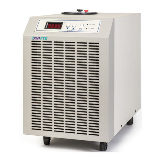
Introduction RS Series Chillers are portable, caster mounted systems that provides temperature controlled fluid over a wide range. All FTS chillers feature innovative design, high-quality construction, and high reliability components. This chiller will reliably serve your cooling needs for years to come. -
Page 8: Installation
Chapter Installation Physical Location The area where you place the unit should be smooth, level, and capable of safely supporting the weight of the machine. Space should be provided so that air can properly circulate around the unit. If obstacles are blocking the airflow, the compressor may overheat. This reduces performance, and can lead to early compressor failure. -
Page 9: Selecting A Process Fluid
Which fluid you choose will depend partly on what temperature range you require. Ethylene Glycol and water (60/40 mix) is an inexpensive and readily available fluid for –25°C to +60°C. If you require a fluid outside this temperature range, FTS suggests using HT-30 Silicone Oil for –60°C to +100°C. -
Page 10: Process Fluid Properties
Operator’s Manual: RS Series Chiller Chapter 2: Installation Process Fluid Properties Expansion/Contraction It is important to note that some fluids expand as much as 14% from +25 ° C to +125 ° C. Do not confuse contraction of the fluid for fluid losses. Also, open the red vent screw on the reservoir lid when changing the setpoint (the temperature the unit controls at). -
Page 11: Electrical Requirements
Operator’s Manual: RS Series Chiller Chapter 2: Installation Electrical Requirements Only qualified personnel should perform the installation of this unit. The voltage and frequency requirements are specified on the serial tag on the rear of the unit. Standard variances in frequency (+/-3Hz) and voltage (-5%, +10%) are allowed. -
Page 12: High Pressure Bypass Hook-Up (Accessory)
Operator’s Manual: RS Series Chiller Chapter 2: Installation High pressure Bypass Hook-Up (Accessory) The high pressure bypass allows the user to control the pressure of the process fluid going to the application. This is particular can be useful if an application is sensitive to pressure such as a glass jacketed reaction vessel. -
Page 13: Connect To The Process
Operator’s Manual: RS Series Chiller Chapter 2: Installation Connect to the Process FTS provides input and output connections for the process fluid. To tie these lines into your process, you will need: • 1/4” Fittings for 1/4” male pipe thread on the Fluid I/O ports (3/8”... -
Page 14: Operation
Chapter Operation System Preparation • Plug the unit in if it is not already plugged in. • System is now in Idle. • Display will be blank and the amber Power light will be illuminated Start Up • Press I/O button •... - Page 15 Operator’s Manual: RS Series Chiller Chapter 3: Operation NOTE: When changing setpoint, loosen the red vent screw on the reservoir lid to accommodate for the expansion / contraction of the process fluid. Once the chiller stabilizes at a setpoint, tighten the red vent screw. This will help...
-
Page 16: User Menu
Chapter User Menu This unit is equipped with an EDC digital control package. Varying the parameters in the EDC Controller’s User Menu allow the operation of the unit to be fine tuned to meet the needs of a specific application. A variety of parameters such as Ramp Rate, Auto-Power Recovery, High and Low Temperature Alarms, Parameter Lock, Setpoint Limits, readout options, Proportional Control parameters, and several Communications options can all be adjusted from the... -
Page 17: User Menu Layout
Operator’s Manual: RS Series Chiller Chapter 4: User Menu User Menu Layout Operating Mode (Unit is running or in IDLE) SPAn Proportional Control Menu Span Menu Miscellaneous Menu Communication Menu PLOC baud Press & Hold Ramp Rate High Alarm Parameter Lock... -
Page 18: Proportional Control Menu
Operator’s Manual: RS Series Chiller Chapter 4: User Menu Proportional Control Menu Programmed transition rate from old setpoint to new setpoint, in degrees per minute. Ramp Rate is more of a slew limiter, because Ramp Rate the available ramp rate is obviously limited by the thermal load and the pulldown capacities of the refrigeration system. -
Page 19: Span Menu
Operator’s Manual: RS Series Chiller Chapter 4: User Menu Span Menu An alarm can be set to alert the user that the process temperature is too high. Should the HA be triggered, the system will go to FULL COOL and the display will flash HA. The... -
Page 20: Miscellaneous Menu
Operator’s Manual: RS Series Chiller Chapter 4: User Menu Miscellaneous Menu If set to 1, operating parameters may not be changed unless system PLOC is off (not running). Note that if this is set while the unit is running, it Parameter Lock may not be reset unless the system is first turned off. -
Page 21: Communications Menu
Operator’s Manual: RS Series Chiller Chapter 4: User Menu Communications Menu Baud Rate for the RS-232 control communications port may be set according to the table. baud Display Baud Baud Rate 1200 2400 9600 Sbit Stop Bit Next The number of stop bits (1, 1.5, 2) may be selected... -
Page 22: High Fluid Temperature
HA value so that it is above the desired setpoint. If the HA still goes off, check that the thermal load being applied by your process is within the heat removal capacity of this unit. Contact the FTS Service Division if the condition persists. © SP Industries, Inc. MNL-008-A Rev. 009... -
Page 23: Low Fluid Temperature
Then either increase the temperature setpoint to ensure it is set above the low temperature alarm setting (LA), or adjust the LA value so that it is lower than the desired setpoint. Contact the FTS Service Division if the condition persists. -
Page 24: Pid Tuning
Operator’s Manual: RS Series Chiller Chapter 4: User Menu PID Tuning Since each installation has different conditions of operation (ambient temperature, water temperature, different fluid loop length, etc), the factory PID settings do not always provide optimum control at the required temperature setpoint. -
Page 25: It And Dt
Operator’s Manual: RS Series Chiller Chapter 4: User Menu IT and DT Measure the period of the temperature oscillations, peak temperature to peak temperature. time(t) Integral Time ≤ NOTE: This represents the Derivative Time maximum value for derivative time. It can be lowered. -
Page 26: Cpb
Operator’s Manual: RS Series Chiller Chapter 4: User Menu Note the amount the temperature swings above and below the setpoint. The temperature swing is used to figure the proportioning band. Cool Proportioning Band (CPb) CPb = Temperature swing below setpoint + 10% of that temperature swing Example: 2°C below... -
Page 27: Hpb, Cpb, And Db
Operator’s Manual: RS Series Chiller Chapter 4: User Menu HPB, CPB, AND DB (RS33 – Heat option only) Note the amount the temperature swings above and below the setpoint. These temperature swings are used to figure the proportioning bands and the dead band. -
Page 28: Rs-232 Communications Programmer's Reference
Programmerʹs Reference OVERVIEW The MPC and EDC controllers are used in a variety of cooling products manufactured by FTS. The commands used by a specific system will vary per the descriptions at the end of this reference, but the operational aspects, hardware and software, of the interface are consistent across the product line. - Page 29 Operator’s Manual: RS Series Chiller Chapter 5: RS232 Communications COMMUNICATION DATA All programmable, selectable, or switchable functions of the target system are accessible via the RS-232, with the exception of the RS-232 configuration itself, which may not be programmed from the host.
- Page 30 Operator’s Manual: RS Series Chiller Chapter 5: RS232 Communications All data received by the target system will be presented by the host system as a character string of one of the following formats: 1) Absolute Command Basic system functions/commands will consist of a fixed character string.
- Page 31 Operator’s Manual: RS Series Chiller Chapter 5: RS232 Communications TRANSMITTED DATA It is anticipated that in a remote-controlled operation of the target system, the actual controlling "device" may be either a computer with a software program, or a human being working interactively.
- Page 32 Operator’s Manual: RS Series Chiller Chapter 5: RS232 Communications TRANSMITTED DATA FORMAT ACKNOWLEDGE The explicit characters "OK" acknowledge receipt of a valid message, followed by 11 spaces (not counting the space for line continuation, described below). ERROR The line begins with the character "E", followed by a 3-digit decimal value defining the error number.
- Page 33 Operator’s Manual: RS Series Chiller Chapter 5: RS232 Communications Example: Received string: Transmitted message: OK <CR> F057=-0030.00!<CR> (Function #57, Setpoint, is currently -30 degrees) TERMINATOR The exclamation point ("!") is issued prior to the last <CR> to indicate "end of message", so that multiline messages may be accommodated.
- Page 34 Operator’s Manual: RS Series Chiller Chapter 5: RS232 Communications CLRALARM Clear alarm conditions from the system, if any exist. Restore ALMCODE? to 0. If the condition creating the alarm state persists, however, the system will restore the alarm until that condition is corrected.
- Page 35 Operator’s Manual: RS Series Chiller Chapter 5: RS232 Communications FSPANH? {F021} Query the high temperature limit (degrees) established by the FLUID definition. FSPANL? {F022} Query the low temperature limit (degrees) established by the FLUID definition. GNREM= / GNREM? {F023} Adjust or query the calibration gain factor applied to the remote [external] temperature sensor.
- Page 36 Operator’s Manual: RS Series Chiller Chapter 5: RS232 Communications LOOP2? (Service Use) (Not Yet Implemented) {F034} Query existence of a second control loop, in dual-loop systems. MODE? {F035} Query the control configuration of the system (factory-set per configuration). 0 = heat and cool, 1 = cool only, 2 = heat only.
- Page 37 Operator’s Manual: RS Series Chiller Chapter 5: RS232 Communications REFR? {F050} Query state of refrigeration. Returned 0 = off, 1 = 1st stage on, 2 = 2nd stage on (if cascade system). REFRHRS? {F078} Query running hours of system refrigeration.
- Page 38 Operator’s Manual: RS Series Chiller Chapter 5: RS232 Communications TIME= / TIME? (Not yet implemented) {F066} Set or query time of day in Real-Time Clock option. TRIPLI? (Service use) {F067} Query factory-programmed trip temperature of suction line, to determine operation of the liquid injection valve.
- Page 39 Operator’s Manual: RS Series Chiller Chapter 5: RS232 Communications MPC Code 3: Insufficient cooling water in water-cooled system. EDC Code 6: MPC Code 4: Stage 1 Refrigeration is not powered, as determined by current sensors. This failure can be due to [internal] overtemp cutouts, trip of a circuit breaker, etc.
- Page 40 Operator’s Manual: RS Series Chiller Chapter 5: RS232 Communications Break Error. See E004. E008 Group 1 Errors: General Parsing and Transmission Errors Transmit Buffer Overflow. Requests for information (queries) result in information E010 being buffered faster than it can be transmitted to the host (Baud-Rate dependent). 1KB buffer exceeded.
- Page 41 Operator’s Manual: RS Series Chiller Chapter 5: RS232 Communications Start Error. System already started has received a "START" command. E042 Not a User Function. Certain operational commands are defined to the system and E043 reserved for factory use. Error 43 reports use of such a command without proper security access.
-
Page 42: Maintenance
Chapter Maintenance Warning! Hazardous voltages. Risk of electric shock. Disconnect all power before servicing this unit. Refer servicing to qualified service personnel. Caution! Power supply phases to this unit must be in correct sequence Notice! Only qualified personnel should perform maintenance on the refrigeration system itself, and only EPA certified technicians may evacuate or charge refrigerants. - Page 43 Operator’s Manual: RS Series Chiller Chapter 6: Maintenance Lockout/Tagout Procedure To prevent accidental or unauthorized starting of this unit during maintenance, disconnect the power cord and install an appropriate lockout device on the end of the power cord. The necessary equipment should be available to allow the user to comply with OSHA 29 CFR 1910.147 (Control...
- Page 44 Operator’s Manual: RS Series Chiller Chapter 6: Maintenance Fuse Replacement Warning! Hazardous voltages. For continued protection against risk of fire or shock, replace fuses only with those of same type and rating. Qualified service personnel must perform replacement. Notice! Only qualified personnel should perform maintenance on the system.
- Page 45 Operator’s Manual: RS Series Chiller Chapter 6: Maintenance Cleaning Warning! Hazardous voltages. Risk of electric shock. Disconnect all power before servicing this unit. Refer servicing to qualified service personnel. Notice! Only qualified personnel should perform maintenance on the system. Caution! Proper safety equipment such as eye and face protection, gloves and dust mask should be used.
- Page 46 Operator’s Manual: RS Series Chiller Chapter 6: Maintenance Draining Fluid Always use caution when handling fluids, filling or draining the system reservoir, or working in or around the chiller. Always wear protective eyewear when operating the chiller. The user may need to drain the unit for any number of reasons: to replace the fluid, to change the type of fluid used, during maintenance, during repairs, etc.
-
Page 47: Troubleshooting
Chapter Troubleshooting NOTICE! Only qualified personnel should perform maintenance on the refrigeration system, and only EPA certified technicians should evacuate or charge refrigerants. PROBLEM POSSIBLE CAUSE SOLUTIONS UNIT WILL NOT Power is not connected properly Have electrician check power connections START Breaker at the wall is in the "off"... - Page 48 If this confirms a leak, have the system leak checked, repair leak, and recharge system to proper level. Contact the FTS Service Dept. for assistance in leak checking and charging the system if needed. Ball valve is closed...
- Page 49 Operator’s Manual: RS Series Chiller Chapter 7: Troubleshooting Restrictions in the system will not Use larger line sizes. Replace pump with pump allow needed flow with supplied pump capable of supplying needed flow with the given plumbing restrictions. Check with factory for warranty...
-
Page 50: Service
FTS Warranties and Service Agreements The FTS Service Division was founded in January of 1971. Our technicians are fully trained to service all electrical, refrigeration, liquid, vacuum, air, and vapor control systems manufactured and sold by FTS. We service all FTS products throughout the world from our home office located at the FTS manufacturing facility in Stone Ridge, New York. -
Page 51: Standard Warranty
Any factory approved changes or extensions to this warranty should be received in writing from FTS and filed with this warranty. If your system is eligible for coverage, please review this warranty thoroughly and contact the FTS Service Division with any questions you may have. -
Page 52: Service Options
This plan provides our customers with one or two onsite visits per year. We would perform a thorough preventative maintenance on your FTS equipment. You will be provided with a PM checklist and a certificate of calibration, which is traceable to N.I.S.T. The purchase of this plan also provides discounted parts and labor rate for additional service if deemed necessary at the time of the PM. -
Page 53: Return Of Fts Equipment
Chapter 8: Service & Warranties Return of FTS Equipment If it is necessary to return the equipment to our factory, please contact the FTS Service Division at (800) 722-7721 for a Return Authorization (RA) number, and instructions on returning the unit. Please provide the model number, serial number, and order number.
Need help?
Do you have a question about the RS Series and is the answer not in the manual?
Questions and answers