Advertisement
Quick Links
Advertisement

Summary of Contents for Home Gym SA-006SM
-
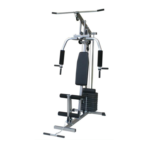
Page 1: Home Gym
HOME GYM SA-006SM User Instructions... -
Page 2: Safety Instructions
SAFETY INSTRUCTIONS WARNING : To reduce the risk of serious injury,read the following safety instructions before using the product. 1.Read all the instructions in this manual before using the product.Only use this product in the manner described in this manual.Keep this manual for the entire life of the product. 2.This device must be assembled by one or two adults. -
Page 3: Care And Maintenance
Before starting any exercise or conditioning program you should consult with your personal physician to see if you require a complete physical exam. This is especially important if you are over the age of 35, have never exercised before, are pregnant, or suffer from any illness. CARE AND MAINTENANCE: In order to prevent perspiration from damaging the seat cover, use a towel or wipe off the seat cover after each use. - Page 4 Assembly 1 0 × 56mm ¢ M10 × 20mm M10 × 45mm M8 × 65mm M8 × 15mm M10 × 65mm M10 × 60mm M12 × 120mm M8 × 40mm...
-
Page 5: Parts List
Assembly PARTS LIST Item # Description Q’ty Item # Description Q’ty Mid-empty Plug 2pcs Front Base Frame 1pcs Back Base Frame 1pcs 45 Outside-End Plug 2pcs Main Frame 1pcs Pulley Fastness Bush(Big) 4pcs Front Suppor t Frame 1pcs Pulley Fastness Bush(Small) 4pcs 45 Square End Plug 5pcs Leg Extension Frame... - Page 6 Assembly Carefully unpack each component, checking against the parts list that you have all the necessary parts to complete the assembly of your product. Please note that as part of our production checking and for your convenience, all tube caps where necessary have been fitted in the pre-packing stage.
- Page 7 Assembly Stage B. 4). Slide the 2 Rubber Cushion (27) onto the Weight Guide Tubes (06) followed by the 9 Weight Stacks (22). 5). Take the Selector Shaft (07) and fit the Selector Shaft Bush (25) and Selector Shaft Pin (24) as shown. Slide the Top Weight Plate (23) onto the Weight Guide Tubes (06) and locate the Selector Shaft (07) in position, setting the Top Weight Plate (23) onto the top of the Weight Plate (22).
- Page 8 Assembly Stage C. 6). Lay the Upper Cross Beam (09) onto the Main Frame (03) and connect them using 2 x M10 x 65mm Hex Bolts (56), 4 x M10 Washers (63) and 2 x M10 Nylon Nuts (66). 7). Connect the Weight Guide Tube(06) to the Upper Cross Beam (09) using 2 x M10 x 20mm Hex Bolt (54), 2 x M10 Washers (63).
- Page 9 Assembly Stage D. 11). Put all tube caps (41) x 2,(45) x 1 and (40) x 2 into the each tube as shown. 12). Put 4 x the Oil Bush(big)(48) into the Press Bar (16) as shown.. StageE. 13). Connect the Press Bar (16) to the Upper Cross Beam (09) using M12 x 120mm Hex Bolt (59), 2 x M12 Washers (62) and M12 Nylon Nuts (65).
- Page 10 Assembly Stage F. 17). Fit the Back Cushion (21) to the Main Frame (03) using 2 x M8 x 65mm Hex Bolts (60) and 2 x M8 Washers (64). 18). Connect the Front Support Frame (04) to the Front Base Frame(01) using M10 x 65 Hex Bolt (56),2 x M10 Washers (63) and M10 Nylon Nut (66).
- Page 11 Assembly 63 58 64 67 63 7 37 6...
- Page 12 Assembly CABLE ASSEMBLY 22).START WITH THE TOP LONG CABLE 2370mm (52) START BY THREADING THE END OF THE CABLE WITHOUT THE BALL OVER PULLEY NO.1,OVER PULLEY NO.2, DOWN AND AROUND PULLEY NO.3 IN PULLEY NO.1,OVER PULLEY NO.2,DOWN AND AROUND PULLEY NO.3 IN FLOATING PULLEY LOCK,UP AND OVER PULLEY NO.4 AND DOWN AND ATTACH TO WEIGHT STACK WITH M12 BOLT &...
- Page 13 Assembly Correct Shackle Indication Point A: This position can not assemble with Shackle. Point B: This is correct shackle assembled position. The shackle connected with cable and hook where fixed on bottom tube. Please refer drawing in page 10. Point C: Incorrect shackle position. If you assembled in wrong position, you will see the first upper weight stacks can not touch second one.
Need help?
Do you have a question about the SA-006SM and is the answer not in the manual?
Questions and answers