
Summary of Contents for Digital Control Incorporated DigiTrak LT
- Page 1 ™ Directional Drilling Locating System Operator’s Manual IGITAL ONTROL dci@digital-control.com NCORPORATED www.DigiTrak.com...
- Page 2 Digital Control Incorporated. Limited Warranty All products manufactured and sold by Digital Control Incorporated (DCI) are subject to the terms of a Limited Warranty. A copy of the Limited Warranty is included at the end of this manual; it can also be obtained by contacting DCI Customer Service, 425-251-0559 or 800-288-3610, or at DCI's website, www.digitrak.com.
- Page 3 IGITAL ONTROL NCORPORATED Contact Us United States 19625 62nd Ave S, Suite B103 DCI Headquarters Kent, Washington 98032, USA +1.425.251.0559 / 1.800.288.3610 +1.425.251.0702 fax dci@digital-control.com Australia 2/9 Frinton Street Southport QLD 4215 +61.7.5531.4283 +61.7.5531.2617 fax dci.australia@digital-control.com China 368 Xingle Road Huacao Town Minhang District Shanghai 201107, P.R.C.
-
Page 4: Dear Customer
As the horizontal directional drilling industry grows, we’re keeping our eye on the future to develop equipment that will make your job faster and easier. Visit us online any time to see what we’re up to. We welcome your questions, comments, and ideas. Digital Control Incorporated Kent, Washington 2013 See our DigiTrak Training Videos on YouTube at www.youtube.com/dcikent. -
Page 5: Table Of Contents
IGITAL ONTROL NCORPORATED Table of Contents Safety Precautions and Warnings ......................... 7 General ..............................7 Equipment and Battery Disposal ......................8 Pre-Drilling Testing ..........................8 Interference .............................. 8 Equipment Maintenance .......................... 9 Introduction..............................10 Power Requirements ..........................11 Environmental Requirements ........................ 11 Receiver .............................. - Page 6 IGITAL ONTROL NCORPORATED Confirmation of Exact Heading and Transmitter Position ..............48 Finding the RLP ..........................48 Limited Warranty ® Operator’s Manual DigiTrak ™...
-
Page 7: Safety Precautions And Warnings
IGITAL ONTROL NCORPORATED Safety Precautions and Warnings Carefully review this manual and be sure you always operate your DigiTrak locating system properly to obtain accurate depth, pitch, roll, and locate points. If you have any questions about the operation of the system, please contact DCI Customer Service for assistance. -
Page 8: Equipment And Battery Disposal
IGITAL ONTROL NCORPORATED DigiTrak locating systems cannot be used to locate utilities. Continued exposure of the transmitter to heat due to frictional heating of the drill head can cause inaccurate information to be displayed and may permanently damage the transmitter. Remove the batteries from all system components during shipping and prolonged storage;... -
Page 9: Equipment Maintenance
IGITAL ONTROL NCORPORATED Interference at the remote display may also occur from other sources operating nearby on the same frequency, such as car rental agencies using their remote check-in modules or other directional drilling locating equipment. Background noise must be minimal and signal strength must be at least 150 points above the background noise during all locating operations. -
Page 10: Introduction
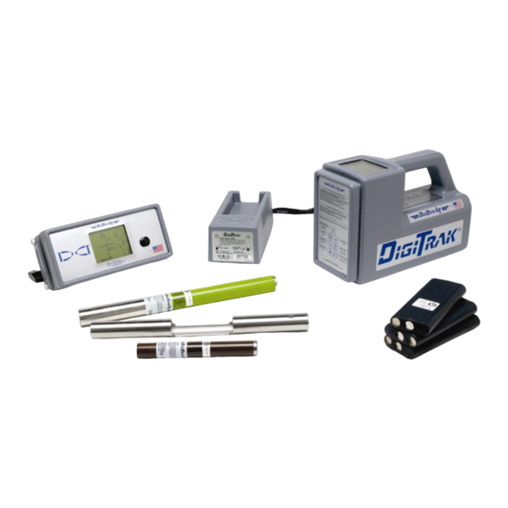
Battery Packs DigiTrak LT Locating System The DigiTrak LT Locating System is used to locate and track the drill head during horizontal directional drilling (HDD) operations. The system consists of a handheld receiver, a transmitter, which is placed in the drill head, and a remote display. The receiver and remote are powered by a rechargeable DCI battery pack, and a battery charger is also included with the system. -
Page 11: Power Requirements
Device Voltage Current DigiTrak LT Receiver 14.4 V DC (nominal) < 0.25 A DC DigiTrak LT Remote Display 14.4 V DC (nominal) < 0.25 A DC DigiTrak LT Battery Charger 12–28 V DC < 2.0 A DC 100–240 V AC, 50/60 Hz... -
Page 12: Receiver
Trigger Handle Front Panel Battery Compartment DigiTrak LT Receiver (side view) Display Screen The LT receiver is a hand-held unit used for locating and tracking an LT transmitter emitting a signal at 12 kHz. The receiver converts signals from the... -
Page 13: Main Display Screen
Receiver Main Display Screen When the LT receiver is on, the display screen usually shows the standard locating mode display (see figure below), which is the default display. The display symbols that appear on the locating screen are identified in the figure below and described in the “Standard Display Screen Symbols” table on the next page. -
Page 14: Standard Display Screen Symbols
Receiver Standard Display Screen Symbols – Appears when the height-above-ground function is on and Height-Above-Ground Icon shows the current height setting. – Represents a bird’s-eye view of the receiver. This icon is referred to as Locating Icon the “box” when using the target-in-the-box and line-in-the-box locating techniques. –... -
Page 15: Power On/Off
Receiver Power On/Off On – To turn the LT receiver on, pull and hold the trigger in for 2 seconds and release. You will briefly see a test screen, followed by a set of numbers that represent the firmware version in the receiver. Then you will go to the standard locating mode display screen. -
Page 16: Accessing And Changing Menu Settings
Receiver Accessing and Changing Menu Settings To access the LT menu functions, you simply click the trigger. Each trigger click advances you to the next menu item. When you stop at a menu, you will see a number that indicates a countdown sequence. To change a menu setting, you hold the trigger in while the counter goes down to 0. - Page 17 Receiver HEIGHT ABOVE GROUND This display menu allows you to enter a height-above-ground measure- ment so that you can measure the transmitter depth without having to place the LT receiver on the ground. If the height-above-ground Height function is not on, then you must place the receiver on the ground to Above take depth measurements.
- Page 18 Receiver There are three options in the height-above-ground menu: “On” turns on the height-above-ground function and sets it to the last value that was used. “Off” turns off the height-above-ground function. “Set” allows you to set or change the height-above-ground value. When you enter the height-above-ground menu, the “On”...
- Page 19 Receiver Height-Above-Ground “Off” Screen 3. Continue to hold the trigger in through the countdown sequence from 2 to 0. 4. Release the trigger when the 0 is displayed, and a checkmark will briefly appear at the bottom of the screen indicating this option has been selected. The height-above-ground function has now been turned off, and you will be returned to the locating screen.
- Page 20 Receiver 6. Continue to hold the trigger in through the countdown sequence from 2 to 0. 7. Continue to hold the trigger in, and the height-above-ground measurement will display starting at 12 in. (30 cm) and then counting up in 1-inch (2-cm) increments. 8.
- Page 21 Receiver Telemetry Channel Setting 3. When the counter reaches 0, you will see a checkmark at the bottom of the display. 4. While still holding the trigger in, the channel settings will cycle through all nine settings—Off, 1, 2, 3, 4, 5, 6, 7, 8.
- Page 22 Receiver 3. When the counter reaches 0, the light bulb will either light up as the backlight comes on or it will become unlit and the backlight will turn off. 4. Release the trigger to return to the standard locating mode screen. NOTE: The backlight automatically comes on for a few seconds at startup, and then it defaults to the off setting, even if you have reset it previously.
- Page 23 Receiver To calibrate the receiver: 1. Using a tape measure, place the receiver on the ground parallel to the transmitter (in housing) so that the distance from the centerline of the transmitter to the inside edge of the receiver is 10 ft (3.05 m), as shown in the figure given below.
- Page 24 Receiver 7. You should see a depth reading that matches this measured distance, which in our example would be 6 ft (1.83 m).* 8. Repeat the above two steps in at least two more locations. DEPTH UNITS This display menu allows you to set the LT system to display values (depth and temperature) in either or “in”...
- Page 25 Receiver PITCH UNITS This display menu allows you to set the LT system to display pitch values in either degrees or percent of slope. 1. Click the trigger to advance to the pitch units menu. The display will indicate the current setting. 2.
-
Page 26: Transmitter
IGITAL ONTROL NCORPORATED Transmitter Types of LT Transmitters The LT transmitter fits inside the drill housing and transmits information regarding the drill head location, position, and heading. The transmitter emits electromagnetic signals at a frequency of 12 kHz that the receiver “hears”... -
Page 27: Transmitter Housing Requirements
Transmitter Transmitter Housing Requirements To achieve maximum range and battery life for all of DCI’s transmitters, the slots in the housing must be long enough and correctly positioned. Slot measurements should always be taken from the inside of the housing. DCI recommends at least three slots equally spaced around the circumference of the housing. The slots should be at least 1/16 or 0.0625 in. -
Page 28: Transmitter Battery Power
Transmitter Transmitter Battery Power The LT transmitters are battery powered. The long-range LX trans- mitter is powered by two C-cell alkaline batteries, and the short- range LS transmitter is powered by one AA alkaline battery. Transmitter Battery Status Display Symbol The transmitter battery icon at the bottom of the display screen con- tinuously shows the status of the transmitter battery power using progress bars that decrease as the battery power is used. -
Page 29: Sleep Mode (Automatic Shutoff)
Transmitter The transmitter also has a temperature overheat indicator (temp dot) that has an outer yellow ring with a 1/8-inch (3-mm) white dot in the center. This temp dot is located on the stainless-steel front end cap. The temp dot should be white if the transmitter has not been exposed to excessive heat. If the temp dot is silver or gray, it indicates the transmitter has been exposed to heat but not in excess of the specifications. -
Page 30: Remote Display
DigiTrak LT Remote Display The DigiTrak LT remote display, which is located at the drill rig, receives signals from the LT receiver and displays that information on a screen very similar to the receiver display screen. The remote display has a main display screen and five menu options (power on/off, telemetry channel settings, backlight on/off, depth unit selection, and pitch unit selection). - Page 31 Remote Display The main display screen indicates when the receiver is over the transmitter or the locate line (LL) by showing arrows above and below the depth value, as shown below. The receiver display will show the line in the box. Arrow pointing to tool head indicates the line is in the box and the...
-
Page 32: Remote Display Menus
Remote Display Remote Display Menus Power On/Off With the power on/off menu displayed, as shown in the picture below, hold the button in for the count- down sequence from 3 to 0 to turn the unit off. The remote display will automatically shut itself off if no data is received for 15 minutes. -
Page 33: Depth Units
Remote Display Depth Units The depth units menu, shown in the picture below, allows you to set the remote display to show values for feet/inches or “in” for inches only and °F) or metric (depth and temperature) in either English (FT for meters/centimeters and °C) units. -
Page 34: Battery Charger
IGITAL ONTROL NCORPORATED Battery Charger Rechargeable Battery Pack Unexposed Terminal DO NOT EXPOSE Control Panel AC Adapter AC Power DC Power Cord Cord Negative Terminal Positive Terminal Battery Charger General Description The DCI battery charger unit, which includes AC and DC power cords and an AC adapter, is provided with the LT system, along with three rechargeable DCI battery packs. -
Page 35: Ac/Dc Power Setup
Battery Charger AC/DC Power Setup To install either the AC adapter or the DC power cord, insert the charger plug into the power port on the back of the battery charger (see photo to right) and rotate a quarter turn in either direction to lock it in place. If using AC power, connect the AC power cord to the power adapter, then plug the cord into the AC power receptacle (wall outlet). - Page 36 Battery Charger NOTE: If a battery becomes drained below 4 V, the charger will not immediately recognize the battery. Leave the battery in the charger and press the charge button. Within a few minutes, the red light will begin to blink indicating the charger has recognized the battery.
- Page 37 Battery Charger Notes ® Operator’s Manual DigiTrak ™...
-
Page 38: Locating Instructions
NCORPORATED Locating Instructions The DigiTrak LT Locating System is easy to use, but there are basic principles that must be understood before you begin to operate the system. This section gives important information regarding the depth or slant distance; the locate points and locate line; the geometry of these elements with respect to the transmitter;... -
Page 39: Effects Of Depth, Pitch, And Topography On Distance Between Flp And Rlp
Locating Effects of Depth, Pitch, and Topography on Distance Between FLP and RLP Because of the transmitter’s field shape, the deeper the transmitter is, the further apart the FLP and RLP will be. The distance between the FLP and RLP with respect to the location of the LL is also a function of the transmitter pitch and the topography. -
Page 40: Marking Locate Points
Locating Marking Locate Points The front and rear locate points (FLP and RLP) and the locate line (LL) must be found and accurately marked during the locating procedure. To mark a locate position after you have found it, stand with the receiver level directly above the locate point. -
Page 41: Locating The Transmitter - Standard Method
Locating Locating the Transmitter – Standard Method With the LT system, you can locate the transmitter and its heading while it moves, whether standing in front of it, behind it, or toward the side. You can also locate the transmitter facing either toward or away from the drill rig. -
Page 42: Finding The Flp
Locating Finding the FLP 1. Stand out in front of the drill head (facing the drill) at a distance of approximately one drill rod length. 2. As you approach the FLP, the target appears in the top left corner of the display and the depth number decreases. -
Page 43: Finding The Transmitter And The Ll
Locating 4. Turn the receiver 90° from the transmitter heading while holding the receiver steady and level, and again center the target in the box by moving the receiver forward or backward as needed. This is the FLP, which is where the transmitter will end up if it does not get a steering command. 5. -
Page 44: Confirmation Of Exact Heading And Transmitter Position
Locating Arrow pointing to tool head indicates the line is in the box and the receiver is above the transmitter or LL. LL Moving Toward the Box Line in the Box NOTE: The arrow that appears below the depth measurement and that points to the transmitter also appears on the remote display. -
Page 45: Finding The Rlp
Locating Finding the RLP 1. While standing above the transmitter still facing the drill, continue walking toward the drill; the target will appear in the top left corner of the display and the depth will increase. Target in Top Left Corner 2. -
Page 46: Plus/Minus ("+/-") Locating Method
Locating Plus/Minus ("+/–") Locating Method The plus/minus method is the same as that used in DCI’s Mark series receivers for finding the front and rear locate points. This method is similar to the standard locating method except here you hold the trigger in and use the signal strength and plus/minus signs for locating. -
Page 47: Finding The Transmitter And The Ll
Locating 3. Continue to walk forward until the "+" sign changes to a "–". Note that the target has moved into the box and the signal strength has increased. Target in the Box 4. Turn the receiver 90° from the transmitter heading while holding the receiver steady and level, and again find the point where the "+"... - Page 48 Locating 4. Release the trigger to see the depth display. Height-Above-Ground Setting Replaces Telemetry Channel Setting Transmitter Pitch Replaces Temperature Arrow pointing to tool Reading head indicates the line is in the box and the receiver is above the transmitter or LL. Depth Screen NOTE: The arrow that appears below the depth measurement and that points to the transmitter also appears on the remote display when the line is in the box.
- Page 49 Locating 2. Walk forward until the "+" sign changes to a "–" sign. Note that the target has moved into the box. Target in the Box 3. Turn the receiver 90° from the transmitter heading while holding the receiver steady and level, and find the point where the "–"...
-
Page 50: Limited Warranty
LIMITED WARRANTY Digital Control Incorporated ("DCI") warrants that when shipped from DCI each DCI Product will conform to DCI’s current published specifications in existence at the time of shipment and will be free, for the warranty period (“Warranty Period”) described below, from defects in materials and workmanship. - Page 51 LIMITATION OF REMEDIES AND LIABILITY In no event shall DCI or anyone else involved in the creation, production, or delivery of the DCI Product be liable for any damages arising out of the use or inability to use the DCI Product, including but not limited to indirect, special, incidental, or consequential damages, or for any cover, loss of information, profit, revenue or use, based upon any claim by User for breach of warranty, breach of contract, negligence, strict liability, or any other legal theory, even if DCI has been advised of the possibility of such damages.
Need help?
Do you have a question about the DigiTrak LT and is the answer not in the manual?
Questions and answers