Table of Contents
Advertisement
WARRANTY
Warranty service covers a period of one year from the date of original purchase.
In case of technical failure within one year, our service center or sales outlet free of
charge will provide repair service.
We charge customers for repair after the one-year warranty period has been expired.
Provided that against any failure resulted from the user's negligence, natural disaster
or accident, we charge you for repairs regardless of the warranty period.
For more professional repair service, be sure to contact our service center or sales
outlet.
Advertisement
Table of Contents

Subscribe to Our Youtube Channel
Summary of Contents for EZ Digital FC-3000
- Page 1 WARRANTY Warranty service covers a period of one year from the date of original purchase. In case of technical failure within one year, our service center or sales outlet free of charge will provide repair service. We charge customers for repair after the one-year warranty period has been expired. Provided that against any failure resulted from the user’s negligence, natural disaster or accident, we charge you for repairs regardless of the warranty period.
- Page 2 3. This equipment should be used with a triple line power cord for safety. 4. For quality improvement the exterior design and specification of the product can be changed without prior notice. 5. If you have further questions concerning use, please contact the EZ Digital service center or sales outlet Safety Summary Please take a moment to read these operating instructions thoroughly and completely before operating this instrument.
-
Page 3: Table Of Contents
CONTENT 1. PRODUCT DESCRIPTION 1-1. Introduction ------------------------------------------------------ 1-2. Technical Specifications -------------------------------------- 1-3. Equipment Ratings --------------------------------------------- 1-4. Supplied Accessories ------------------------------------------ 2. INSTALLATION 2-1. Initial Inspection ------------------------------------------------- 2-2. Connecting AC Power ----------------------------------------- 2-3. Cooling and Ventilation ---------------------------------------- 2-4. Position ------------------------------------------------------------ 2-5. Warming-Up ------------------------------------------------------ 3. -
Page 4: Introduction
7 digit display with one second gate time due to uniquely developed LSI as well as the expanding/reciprocal system. It covers a frequency range from 0.1Hz to 3.3 GHz (FC-3000: 3.3GHz, FC-7150U, FC-7150: 1.5GHz, FC-7015U,FC-7015: 100MHz) based on 10MHz time base T.C.O (temperature controlled oscillator) and also... -
Page 5: Technical Specifications
1-2. Technical Specifications INPUT A CHARACTERISTICS - FREQUENCY RANGE : 0.1Hz to 100MHz (DC Coupled) 30Hz to 100MHz (AC Coupled) - SENSITIVITY : 0.1Hz to 100MHz: 30mV - COUPLING : AC or DC Selectable : 1 M Ω Resistance, Shunted by < 40pF - IMPEDANCE - ATTENUATOR : x 1 or x 10 Switch Selectable... - Page 6 <FC-3000, FC-7150, FC-7015 only> - MAX. INPUT VOLTAGE LEVEL FIG 1. MAX. Input Level. (input A,B) INPUT B. CHARACTERISTICS <FC-7150U, FC-7015U> - FREQUENCY RANGE : 0.1Hz to 100MHz (DC Coupled) 30Hz to 100MHz (AC Coupled) - SENSITIVITY : 0.1Hz to 100MHz: 30mV...
- Page 7 : 50 Ω ± 5% - IMPEDANCE - MAX. INPUT LEVEL : 3 Vrms sine wave <FC-3000> - FREQUENCY RANGE : 80 MHz to 3.3 GHz - SENSITIVITY : 80 MHz to 2.0 GHz: 10 mV 2.0 GHz to 3.0 GHz: 20 mV 3.0 GHz to 3.3 GHz : 35mV...
-
Page 8: Equipment Ratings
: Approx. 2.0 kg. 1-3. Equipment Ratings Power & Fuse Ratings Power Max. Input Voltage Fuse FC-7150U,FC-7015U FC-3000, FC-7150, FC-7015 103 ∼ 126V AC(50/60Hz) F 0.5A 250V 206 ∼ 252V AC(50/60Hz) F 0.25A 250V Operating Environment TEMPERATURE : 0 ° C to + 40 ° C (Accuracy Specified at 25° C ± 5 ° C) HUMIDITY : Up to 85% to 40°C without temperature extremes... -
Page 9: Supplied Accessories
1-4. Supplied Accessories Operation Manual ----------------------------------------------------------------------------- 1 BNC cable -------------------------------------------------------------------------------------- 1 Power cord-------------------------------------------------------------------------------------- 1 Spare Fuse-------------------------------------------------------------------------------------- 1 Specifications are subject to change without notice. 2. INSTALLATION 2-1. Initial Inspection This instrument was carefully inspected both mechanically and electrically before shipment. It should be physically free of damage. To confirm this, the instrument should be inspected for physical damage in transit. -
Page 10: Operation
3. OPERATION 3-1. Controls, indicators and connectors 3-1-1. FC-7150U, FC-7015U Universal Counter FIG 2. FC-7150U FRONT PANEL GATE INDICATOR : The gate light, when lit, indicates the main gate is open and measurement in progress. DISPLAY : 9 digit(O.56") green LED display used for all read readings. - Page 11 INPUT A, BNC : Input for frequency measurements below 100MHz. Female BNC connector terminated in 1 MΩ input resistance, Shunted by < 40pF capacitance. INPUT C, BNC : Input for frequency measurements above 80MHz female <FC-7150U Only> BNC connector terminated in 50Ω. INPUT B, BNC : Input for frequency measurements below 100MHz Female BNC connector terminated in 1 M Ω...
- Page 12 Negative going edge of each signal is selected By the slope switches. g. RATIO (A/B). When this mode is selected, the unit measures the ratio of input A frequency to the input B frequency. POWER SWITCH : Push in the unit ON and push out the unit power OFF. VOLTAGE FUSE POWER MAX...
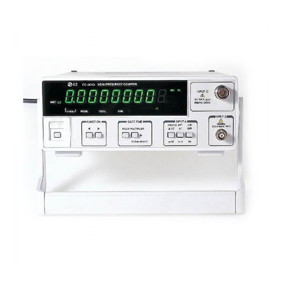
- Page 13 3-1-2. FC-3000, FC-7150, FC-7015 Frequency Counter FIG 4. FC-7150 FRONT PANEL 3GHz FREQUENCY COUNTER FC−3000 INPUT C 3V MAX. RMT G.T 80MHz 3GHz . 0 0 0.1S PRIOD TOTAL FREQ. INPUT A POWER GATE TIME INPUT A FUNCTION 100MHz COUPLE 250V MAX.
- Page 14 A. : When this mode is selected, the counter reads the frequencyof the input A. Resolution is selected using the GATE TIME. b. FREQ. C<FC-3000,7150 >: When this mode is selected, the counter reads the frequency of the input C.All readings are in MHz.
- Page 15 DISCONNECT POWER SUPPLY BEFORE REPLACING FUSE. DO NOT REMOVE COVER. REFER SERVICING TO INT STD OUT EXT STD IN QUALIFIED PERSONNEL. FIG 7 . FC-3000 REAR PANEL Test Equipment Depot - 800.517.8431 - 99 Washington Street Melrose, MA 02176 FAX 781.665.0780 - TestEquipmentDepot.com...
-
Page 16: Operating Instruction
VOLTAGE SELECTOR : Select ac power, 115V AC or 230V AC. AC INLET :For connecting of the supplied ac power INT/EXT TIME BASE SELECTOR : Select the time base, switch position EXT. STD.IN provides a nominal 600Ω input impedance path for an external 10 MHz time base. switch position INT. -
Page 17: Frequency Measurements
3-3-2 INPUT C FC-7150U, FC-7150: 80 MHz to 1.5 GHz FC-3000 : 80MHz to 3.3GHz CAUTION THE MAXIMUM INPUT LIMIT TO THIS INPUT IS 3 Vrms MAXIMUM OVER THE INPUT FREQUENCY RANGE. THE X 10 ATTENUATOR DOES NOT APPLY. -
Page 18: Period Measurements
COUNTER TO INCREMENT AND WHEN THE HOLD IS RELEASED, THE UPDATE COUNT IS DISPLAY. 3-6. RPM (Rotation Per Minute) Measurement <FC-3000, FC-7150, FC-7015> a. Apply the signal to be measured to the input A BNC, and then the counter displays the RPM. Maximum count is 999999999. If this is exceed, the overflow message displays as ”OF”... -
Page 19: Ratio Measurement (A/B)
a. Connect the signal to be measured to the input A and input B. b. Set the T.l(A→B) of function switch. The switch label serves as a reminder that the measurement starts at the input A edge and stops at the input B edge. -
Page 20: Maintenance
c. Select the resolution desired using the gate time switches. d. Frequency ratio is given by the display the gate indicator lights while each measurement is in progress, and the display is updated at the end of each measurement interval. e. -
Page 21: Others
5. OTHERS 5-1. BNC Cable Considerations Accuracy of radio frequency measurements can be affected by connections between signal source and counter. Main considerations are standing waves and shunt cable capacitance. Standing wave is usually present due to reflections when a transmission line is not terminated in its characteristic impedance. -
Page 22: Line Frequency Measurements
5-3. Line Frequency Measurements Use of the attenuator, low pass filter, and/or x10 probe is advisable when measuring line frequency because the high amplitude signal and noise can cause wrong counting. WARNING USE CAUTION IN MEASURING THE LINE FREQUENCY OF AN AC OUTLET. USING THE PROBE TIP ONLY, MEASURE BOTH SIDES OF THE LINE.
Need help?
Do you have a question about the FC-3000 and is the answer not in the manual?
Questions and answers