Table of Contents
Advertisement
Advertisement
Table of Contents

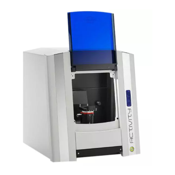
Summary of Contents for Smartoptics Activity 885
- Page 1 Operating Manual A product of smart optics Sensortechnik GmbH...
-
Page 2: Table Of Contents
Table of content 1. Table of content 1. TABLE OF CONTENT 2. LIST OF FIGURES 3. ICONS 4. GENERAL SAFTEY INFORMATION 5. TECHNICAL SPECIFICATION 6. CE DECLARATION OF CONFORMITY 7. GENERAL SAFTEY INFORMATION 8. INSTALLATION 8.1 S ELECTING THE INSTALLATION LOCATION 8.2 U NPACKING AN SCOPE OF DELIVERY 8.3 C... -
Page 3: Table Of Content
Table of content 12.1 C LAMPING THE MODEL 12.2 C REATING A CASE ENTAL 12.3 C ASE STUDY BRIDGE WITH SQUEEZE 13. SYMBOLS 13.1 T HE SYMBOLS 13.2 T VIEWER SYMBOLS OBJECT VIEW 13.3 A CTIVITY ENU OPTIONS 13.4 O ... -
Page 4: List Of Figures
List of figures 2. List of figures 1: S ..........................14 IGURE IDE VIEW OF SCANNER 2: H ........................14 IGURE OLDING POINT OF SCANNER 3: S ..........................14 IGURE CANNER LIFTING POINT 4: M ....................15 IGURE AINS SWITCH ON THE FRONT OF THE DEVICE ...........................16 IGURE SET UP... - Page 5 List of figures ............................45 IGURE SAVE PROJECT 49: 3D-STL D ........................... 46 IGURE ATAFILE 50: T ..............................46 IGURE 51: E ........................... 46 IGURE ND SCANNING PROCESS ......................... 47 IGURE SCANNING PROCESS DONE 53: CAD-I ............................47 IGURE 54: C ...................
-
Page 6: Icons
Useful hints are marked with a light bulb in the operating manual 4. General saftey information Proper use: The Activity 885 scanner is intended for use in performing optical, three-dimensional measurements of human jaw models. It is possible to measure articulated models in order to simulate masticatory movements using corresponding software, as in an articulator. -
Page 7: Technical Specification
Technical specification 5. Technical specification Dimensions 490 mm x 430 mm x 440 mm (BxHxT) Weight 32,2 kg Connection voltage 100-240 V AC, 50/60 Hz Power consumption 80 W Permissible temperature 18-30° C range Measureable objects Plaster model of teeth; plaster colour: white, brown, green Articulated Models Minimum clamping range Diameter 38 mm... -
Page 8: Ce Declaration Of Conformity
This declaration becomes invalid in case of an unauthorized change of the device. Device description: Optical 3D scanner Activity 885 Device type: EU guidelines applicable: machine guideline (2006/42/EC) low valtage guideline (2006/95/EEC) -
Page 9: General Saftey Information
The "Activity 885" scanner has been developed and manufactured in accordance with the applicable safety standards and with the greatest possible care. In spite of this, the risk of an electric shock, overheating or fire due to technical defects in individual components cannot be totally excluded. - Page 10 General saftey information An electronic protection mechanism prevents the motors from starting up unintentionally or continuing to operate when the flap is opened. As there is a theoretical possibility of the protection mechanism failing, this entails a residual risk which you can counter by complying with the following rules of use: 7.1.
-
Page 11: Installation
General saftey information 8. Installation 8.1 Selecting the installation location Before installing the scanner, you should select a suitable installation location. A suitable, stable base (bench, tabletop etc.) should be chosen as an installation location. If you install the computer required for operating the scanner underneath the worktop, the available worktop area should be at least 1.1 m x 0.75 m (front width x depth). - Page 12 General saftey information Scope of delivery: 3D Scanner 1x system base plate 3x spacer plates 1x system adapter plate 1x hex key 1x allen bit set 1x removable object holder 1x power cable 2x USB-cable Software installation CD including calibration data and Operating manual 1x Measuring range template 1x 3D-calibration model...
-
Page 13: Carrying Points
General saftey information 8.3 Carrying points Carrying points are provided to move the device. Please note these specifications. Stand so that one person each is positioned to the left and right of the scanner. Take hold of the scanner with one hand at the bottom front of the scanner and the other hand at the top rear. In this way, the scanner can be safely tilted slightly to the rear Rear carrying points (rear of the device) -
Page 14: Removing The Scanner From The Packing
General saftey information 8.4 Removing the scanner from the packing To remove the scanner from the packaging, one person stands to the left of the scanner and the other person stands to the right. Each person must take hold of the scanner with one hand on the upper support point. Next, tilt the scanner slightly to the rear until you can grip underneath the scanner at the front with your other hand. -
Page 15: Installation
General saftey information 9. Installation 9.1 Installation the scanner Please make sure that the main switch is at the "0" position before installation. Figure 4: Mains switch on the front of the device 1. Connect the device to the USB cables using the USB ports on the rear of the device. Fuse USB camera USB device control... -
Page 16: Installing The Computer
General saftey information Connect the other ends of the USB cables to USB connections on the rear of your computer. Connect the scanner to a power source via the mains connection on the rear. Now switch the scanner on at the mains switch. 5. -
Page 17: Figure 6: Language Selection
General saftey information Figure 6: Language selection Figure 7: Set up/Installation Define the installation location for the software by using the "Browse" button to define the path. The installation program suggests a standardized path that you can use. Having selected the path, please confirm this with "Next". -
Page 18: Figure 8: Select Installation Location
General saftey information Figure 8: Select Installation location Define the software name in the "Select Start Menu Folder" window. Then click on "Next". Figure 9: Start Menu... -
Page 19: Figure 10: Creating A Desktop Symbol
General saftey information Select whether you require a Desktop symbol and confirm with "Next". Figure 10: Creating a desktop symbol Before starting the installation, check your selected settings and chose "Install". The installation starts immediately (Fig. 11). Figure 11: Installation... -
Page 20: Importing Calibration Data
General saftey information Confirm the installation of the driver with "Next". Then complete the installation with "Finish". The drivers have now been installed and the process is completed. Figure 12: Completing the installation 9.4 Importing calibration data The scanner–specific calibration data must be imported during the initial installation. Start the Activity software via the Desktop icon or from the Start Menu. -
Page 21: Figure 14: Selected Folder
General saftey information This tool makes it easier to install the required sensor data. Click "Search" to select the file path (SO-202..). When doing so, select only the parent folder and confirm with "OK". Click "Next". The calibration data is imported into the Activity software. Figure 14: Selected Folder The scanner installation has been completed;... -
Page 22: Calibration Procedure
Calibration procedure 10. Calibration procedure 10.1 3D calibration Each calibrating block is measured industrially. These individual values can be found on the calibration model. Figure 16: individual calibration block These values must be saved in the software after reinstalling the software or replacing the calibration model. -
Page 23: Figure 17: Calibration Model Registration
Calibration procedure Figure 17: Calibration model registration Individual values are indicated on the rear of the calibration model. Please enter these in fields #1 and Confirm the procedure with "OK". Calibration always requires three spacer plates. You can start the 3D calibration only by selecting the start command under the item Options Service... -
Page 24: Basic Information About The Device
If the axis calibration fails, please check the height alignment of the model in the measuring field. 11. Basic information about the device 11.1 Functioning of the Activity 885 The optical scanner with the designation "Activity 880" is used for the three-dimensional measuring of jaw models, in orthodontic and prosthetic applications. - Page 25 Basic information about the device A 3D scan is created as follows: The model to be measured is mounted on the object holder: The model is fixed on the object holder for this. Prescan: The prescan compiles a two-dimensional image of the clamped model. This image serves as a basis for the following scan definition.
-
Page 26: Figure 19: Device Front
Basic information about the device Lid/Ghousing opening Device designation Power switch System drawer Figure 19: Device front USB connection for the camera USB connection for the motor and scanner control Fuse Power cord connection Functional earth Figure 20: Device rear... -
Page 27: Figure 21: Side View
Basic information about the device System extract Figure 21: Side View Figure 22: System Drawer... -
Page 28: Figure 23: Data Plate
Basic information about the device Device serial number CE-marking 3D sensor number Figure 23: Data Plate Use only the USB cables included in the scope of delivery, if possible. These have undergone multiple testing at our company in conjunction with your scanner. Communication problems can result between the scanner and PC if cable lengths over 2 meters are used. -
Page 29: Figure 24: Rotating-Swivelling Unit
Basic information about the device 11.2 Interior Lid/housing opening 3D-sensor (not visible from outside) Swivel unit Object holder/ Model holder Figure 24: rotating-swivelling unit Positioning unit (inside the scanner): The positioning unit contains the fixed base holder on which the object to be measured is fixed as well as a rocker and a rotating unit powered by an electric motor. -
Page 30: Figure 25: Individual Parts Of The Object Holder
11.3 Object holder Individual parts of the object holder The scope of delivery for the object holder of the Activity 885 consists of the following components: Figure 25: individual parts of the object holder Removable object holder for non-articulated jaw models. The model is fastened on the object holder using a clamp. -
Page 31: Figure 26: Object Holder System
Basic information about the device Using the object holder system: The object holder of the Activity 880 primarily comprises a system base plate fixed on a swivelling unit. System base plate Figure 26: Object Holder system In order to ensure an optimum alignment of the model to be scanned in the measuring range, a maximum of three additional spacer plates can be mounted on this. -
Page 32: Positioning The Model On The Object Holder
Basic information about the device Example: Standard model holder for non-articulated model with 2 spacer plates Standard model holder for non-articulated model Figure 27: Object Holder system with the Spacer Plates 11.4 Positioning the model on the object holder Positioning: The correct positioning of the model on the object holder is indispensible for correct measuring results. -
Page 33: Figure 28: Height Alignment With Measuring Range Template
Basic information about the device Incorrect height alignment is one of the most frequent reasons for unsatisfactory scanning results! Figure 28: Height alignment with measuring range template It is not usually necessary to realign each non-articulated model in respect to height. Since you will usually work with one model system in a laboratory, you can work with a standard setting already defined in most cases. -
Page 34: Scanning Procedure
Scanning procedure Using "zero" spacer plates: Should it be necessary to attach a model directly to the base plate, remove the locking plate from the spacer plates using the hex key included in delivery, and place it on the base plate. The number of spacers laid beneath must be entered using the software (see software description). -
Page 35: Case Study: Bridge With Squeeze
Scanning procedure Figure 29: new case Dental DB Information such as customer, patient, technician, etc. is to be entered into these fields. 12.3 Case study: bridge with squeeze This example will demonstrate how to operate the device. Figure 30: "DentalDB case example"... -
Page 36: Figure 31: "Bite 2D Scan
Scanning procedure Case example: In the case example we scan a bridge of 24-26. In the tooth schema, click on the teeth 24, 26 and under scan type select "reduced anatomic cap " and 25 as "pontic reduced ". Teeth 23 and 27 are marked as "neighbouring teeth". For 33 to 37 select "Antagonist" and under "Antagonist type"... -
Page 37: Figure 32: "Bitescan-Preview
Scanning procedure Figure 32: "Bitescan-Preview" Coloured squares will appear simultaneously in the preview. (See fig.33) These squares indicate the scan area of the tooth/ squeeze occlusion. The respective colour scheme is the same as the selected scan strategy/ scan type in the tooth schema on the left-hand side. By pressing the left mouse button, you can slide these squares so that they centre on the respective tooth stump/ squeeze occlusion. -
Page 38: Figure 34: Number Of Spacer Plates
Scanning procedure Figure 34: Number of spacer plates After aligning all scan positions, start the 3D scan with this icon. Figure 35: starting the scan process The scanner now moves the model down automatically, based on the predefined scan strategy, and compiles a number of individual measurements from various perspectives. -
Page 39: Figure 36: 3D-Bitescan
Scanning procedure Figure 36: 3D-bitescan You can rotate, move and zoom the model using the following mouse functions: Rotate model Left/Right mouse button Both mouse buttons Move model Zoom Scroll wheel The software will now prompt you to remove the squeeze occlusion and begin with the model stump scan. -
Page 40: Figure 38: 2D Modelscan
Scanning procedure Figure 38: 2D modelscan Perform the 2D scan again and align the prescribed tooth positions, select the spacer plates and start the 3D scan. (See fig. 33 and 35) The prescan is started and you can then newly define the selection for the occlusion registration in the pre-scan image. -
Page 41: Figure 40: Prompt Notification
Scanning procedure Figure 40: prompt notification Remove all teeth from the saw-cut model, apart from the one required. Close the front flap and click "Continue" or "Continue with axis homing". If "Continue with axis homing" is selected, a new reference travel of the axes, object holder or all axes is first executed before the measurement is continued, after removing the stumps. -
Page 42: Figure 41: Data Set Before Matching
Scanning procedure Figure 41: Data set before matching If the model scan exhibits holes or blurred areas, you can correct these with the rescan function. A green cross is located at the top of the 3D viewer, which can be used to start the "Rescan Mode". (See figure. -
Page 43: Figure 43: "Rescan" Mode
Scanning procedure Area to undergo a rescan Cross hairs next to the area to be scanned Figure 43: "Rescan" mode If you click on the blue start button, any number of rescans can now be performed until all desired areas are recorded. Figure 44: "Rescan"... -
Page 44: Figure 45: "Matching" Process
Scanning procedure For details, such as in interdental spaces, please remove all teeth that impair the sensor's view of the area to be closed, e.g. directly adjacent teeth and segments that are not required for the scan. After completing the scan and cutting the data set to size, you need to perform a matching. To do this, click on the following icon: Figure 45: "matching"... -
Page 45: Figure 46: Data Cut
Scanning procedure Figure 46: data cut Figure 47: tailored data file Save the scan data after cutting the data set to size by clicking the "Save" icon. Figure 48: save project... -
Page 46: Figure 49: 3D-Stl Datafile
Scanning procedure Figure 49: 3D-STL Datafile Um den Scanvorgang abzuschließen müssen beiden Datensätze als STL-Datei vorliegen. You can tell from the coloring of the file tab whether a data set is already "matched", i.e. whether there is an STL. (Blue - individual records, Yellow - STL data set, Grey - 2D scan) (see Fig. -
Page 47: Figure 52: Scanning Process Done
Scanning procedure This means that the scan has been preformed and construction can begin. (See fig. 53) Figure 52: scanning process done Now start the construction with the following icon: Figure 53: CAD-Icon The STL data sets are displayed in the CAD software and construction can begin. -
Page 48: Symbols
Symbols 13. Symbols 13.1 The symbols Activity Icon Perform 3D scan Perform 2D scan Move automatically to the service position Open an existing project or STL file Start the matching process Add a new measurement Add bite Add wax-up Next in Workflow... -
Page 49: The 3D Viewer Symbols (Object View)
Symbols Cut data inside the selection Cut data outside the selection Undo the last cutting action or measurement Open the dialog "Fill holes" Save the last work step (possible if activated blue) Open "Settings" dialog Information on the product End the Activity program 13.2 The 3D viewer symbols (object view) Show camera angle Show front view... -
Page 50: Activity Menu Options
Symbols Show right side Show upper side Show lower side Show data set in isometric alignment Rotate the object around the X axis only Rotate the object around the Y axis only Rotate the object around the Z axis only Normal rotation mode 13.3 Activity Menu options Figure 55: Activity menu options... -
Page 51: Options Settings Matching
Symbols 13.4 Options Settings Matching Figure 56: settings-matching Base: The checkbox is used to activate a cut filter, which cuts the upper and/or lower area of the STL data set. The dimensional unit is millimetres. General settings: The STL surface details and so also the data size are determined by the scan quality. The higher the surface details, the lower the distance between the pixels. -
Page 52: Options Settings General
Symbols 13.5 Options Settings General Figure 57: settings general Save images BMP: A BMP (bitmap) of the relevant recording position is created upon activation. This image, in which the light stripe pattern can also be seen, is also saved in the project directory. - Page 53 Symbols Object colour rescan You can determine the colour in which the last manually added image is to be displayed here. Extra smoothing Smoothes the surface of the 3D object in the viewer additionally. This setting does not have any effect on the 3D measurement.
- Page 54 Symbols This function is necessary for technical support. A log file is written that logs all settings and procedures and issues a detailed error message if problems occur. Fill large holes If sporadic "data holes" appear after a scan, you can close these using the “Fill holes"...
-
Page 55: Options Settings Installation
Symbols 13.6 Options Settings Installation Figure 58: Settings installation Work Folder: The storage location of the scan data can be changed here. All data is created and saved in this folder. Dental System: You can indicate what tooth scheme you prefer in the Dental System. Language: The language of the user interface is set here. -
Page 56: Maintenance And Servicing
Please remember that the scanner is designed exclusively for commercial or industrial use. It must therefore not be taken to public waste facilities for disposal. Please contact your dealer or the manufacturer regarding disposal. You can find out more at www.smartoptics.de by going to Company and then Environment. WEEE registration number: DE47893210... -
Page 57: Imprint
Imprint 17. Imprint Manufacturer: smart optics Sensortechnik GmbH Lise-Meitner- Allee 10 44801 Bochum Germany Please contact your dealer if you have any questions. We reserve the right to make changes due to technical progress.
Need help?
Do you have a question about the Activity 885 and is the answer not in the manual?
Questions and answers