
Related Manuals for wtw Oxi 170


Summary of Contents for wtw Oxi 170
- Page 1 Operating instructions Oxi 170 Oxi 170 mg/l ° REL1 Oxygen Monitor ba24105e08 11/2010...
- Page 2 © Copyright Weilheim 2010, WTW GmbH Reprinting - even as excerpts - is only allowed with the explicit written authorization of WTW GmbH, Weilheim. Printed in Germany. ba24105e08 11/2010...
-
Page 3: Table Of Contents
Contents Oxi 170 - Contents Overview ............67 General features . - Page 4 Contents Oxi 170 4.6.3 Timer for external sensor cleaning system ......99 4.6.4...
-
Page 5: Overview
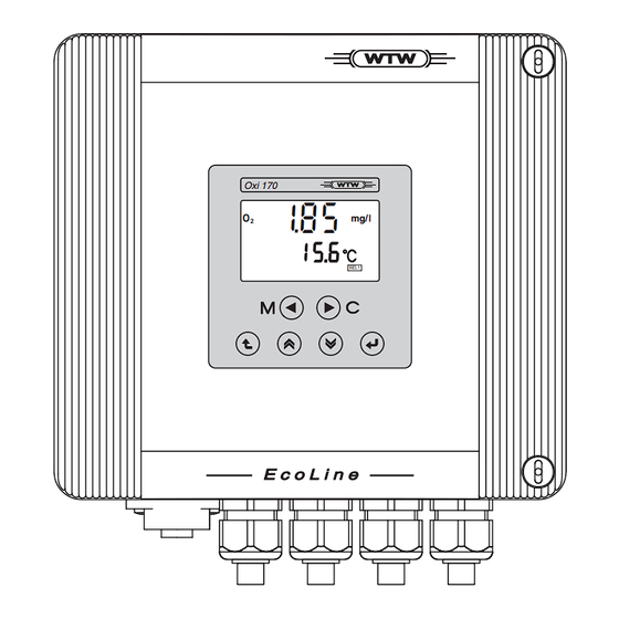
Oxi 170 Overview Overview General features Oxi 170 mg/ l ° REL1 Fig. 1-1 Oxi 170 Watertight housing (IP 66) Display Operating keys Sensor input socket Cable glands ba24105e08 11/2010... -
Page 6: Outputs And Interfaces
2 additional, freely 1 additional analog output configurable relays for the measured temperature value Oxi 170 RT RS as RT option as RT option 1 x RS 485 1.2.2 Freely configurable relay (RT and RT RS option) Both potential-free K1 and K2 relays of the RT and RT RS instrument... -
Page 7: Rs 485 Digital Interface (Rt Rs Option)
Oxi 170 Overview 1.2.4 RS 485 digital interface (RT RS option) The monitor can communicate with other instruments via the RS 485 digital interface of the RS instrument versions. The following operating modes are possible: Master mode ( mode): Unidirectional mode for the output of measured values. - Page 8 Overview Oxi 170 ba24105e08 11/2010...
-
Page 9: Safety Instructions
This operating manual contains essential instructions that have to be followed during the commissioning, operation and maintenance of the Oxi 170 monitor. Thus, it is essential for the operator to read this component operating manual before carrying out any work with the system. -
Page 10: Authorized Use
Safety instructions Oxi 170 Authorized use The authorized use of the Oxi 170 monitor consists solely of stationary measurement in water and wastewater applications, seawater, brackish water and aquacultures. Read the technical specifications in accordance with chapter 8 T . Only operation and use ECHNICAL DATA according to the instructions in this operating manual is authorized. -
Page 11: Installation
Netz Option Option Mains Fig. 3-1 Mounting boreholes of the Oxi 170 The clearances of the boreholes are given in the dimensional drawing in the chapter 8 T . For wall mounting, use the suitable ECHNICAL DATA material (screws, wall plugs, etc.). -
Page 12: Electrical Terminal Strip
Installation Oxi 170 Electrical terminal strip The terminal strip of the Oxi 170 is accessible after the housing cover has been opened: 13 12 11 Sensor/Probe Rec2 Rec1 g f e d Netz Option Option Mains Fig. 3-2 Terminal strip Oxi 170 inside the housing... -
Page 13: Electrical Connection
Seal all open cable glands with matching blind plugs. WARNING Free wires must not protrude into the housing of the Oxi 170. Danger of short-circuit and fire! Touch-proof circuits can also come into contact with dangerous voltages if touched and lead to life threatening situations when working with the Oxi 170. -
Page 14: Line Power Connection
Installation Oxi 170 3.3.2 Line power connection WARNING If the power supply is connected incorrectly, it may represent a danger to life from electric shock. Pay attention to the following points during installation: The monitor must only be connected by an electrician. -
Page 15: Relay Contacts And Current Outputs
Oxi 170 Installation 3.3.3 Relay contacts and current outputs WARNING If external electrical circuits that are subject to the danger of physical contact are incorrectly connected to the relay contacts, there may be a danger of life threatening electric shock. Electrical... -
Page 16: Connecting The Sensors
Installation Oxi 170 Connecting the sensors 3.4.1 Connecting the oxygen (D.O.) sensor WTW online D.O. sensors have a permanently mounted connection cable with a 7-pin plug adapter. Connection Connect the plug adapter of the sensor connection cable with the sensor input jack of the monitor:... -
Page 17: Cable Extension
Oxi 170 Installation 3.4.2 Cable extension The EK 170 cable (order no. 108 206) can be used in conjunction with the KI/S terminal box (order no. 108 606) for cable extension between the sensor/electrode and the monitorand the K 160 cable plug (order no. - Page 18 Installation Oxi 170 ba24105e08 11/2010...
-
Page 19: Operation
Oxi 170 Operation Operation Display Display elements Oxi 170 % mg/l Baud ° Ident Auto REL1 REL2 Upper display line: Measured oxygen value, operator guidance SensCheck symbol Lower display line: Measured temperature value, operator guidance Status displays, depending on instrument status... -
Page 20: Operating Keys
Operation Oxi 170 Operating keys The monitor is operated via the following six keys below the display: Key functions Function Call up measuring mode <M> Start calibration (only active in measuring mode) <C> In measuring mode: Display the sensor slope Confirm current selection <ENTER>... -
Page 21: Operating Levels And General Operating Principles
Oxi 170 Operation Operating levels and general operating principles OPERATING LEVEL (Measurement and calibration) 3.) Password entry for editing (optional) or viewing only with PARAMETERIZATION LEVEL ( ) Parameterization settings CONFIGURATION LEVEL ( ) Configuration settings Fig. 4-1 Operating levels... -
Page 22: Configuration
Operation Oxi 170 Configuration 4.4.1 Call up configuration level Call up the configuration level from the operating level as follows: 1 Press <DOWN>. 2 Press <ENTER>. 3 The menu for the password prompt appears. When delivered, no password protection is set up. In this case proceed to the next operating step by pressing <ENTER>... -
Page 23: Configuration Setting Table
Oxi 170 Operation 4.4.2 Configuration setting table General operating The starting point for the settings is the start display of the configuration instructions level (see section 4.4.1): Swap to the first setting with <ENTER>. Operation: All settings of the following setting table are run through step by step. - Page 24 Operation Oxi 170 Setting table: Setting Selection/Values Explanation (values in bold typeface = values on delivery) Switches the salt content correction on (On) or off (Off, delivery condition). The salt content correction allows for the salinity equivalent entered in the parameter level when calculating the measured value (see section 4.5.2)
- Page 25 Oxi 170 Operation Setting Selection/Values Explanation (values in bold typeface = values on delivery) mg/l / % Measured value range of the REC 1 analog output (D.O. value). After confirming the reC (mg/l or %) selection with <ENTER> you can adapt the upper final value.
- Page 26 Operation Oxi 170 Setting Selection/Values Explanation (values in bold typeface = values on delivery) °C Measured value range of the REC 2 analog output (temperature value). After confirming the reC (°C) selection with (only with RT and RT RS option) <ENTER>...
-
Page 27: Parameterization
Oxi 170 Operation Parameterization 4.5.1 Calling up the parameterization level Call up the parameterization level from the operating level as follows: 1 Press <DOWN>. 2 Press <ENTER>. 3 The menu for the password prompt appears. When delivered, no password protection is set up. In this case proceed to the next operating step by pressing <ENTER>... -
Page 28: Setting Table Of Parameterization
Operation Oxi 170 4.5.2 Setting table of parameterization Overview of the settings Instrument version (main level) Display Description Stan- RT RS dard Salinity equivalent Current output 1 Current output 2 Relay limits Air pressure Site altitude RS 485 interface Password protection... - Page 29 Oxi 170 Operation specific configuration settings. Settings that are not available will be skipped. From any point of the main level press <ESC> to return to the starting point of the parameterization level. From here change to the operating level with <M> or <ESC> or to the configuration level with <UP><DOWN>.
- Page 30 Operation Oxi 170 Setting Selection/Values Explanation (values in bold typeface = values on delivery) Current range and attenuation of the REC 1 current output in rEC operating mode (analog output for the D.O. value). Operating notes: – The setting is carried out in the order: =1 ...
- Page 31 Oxi 170 Operation Setting Selection/Values Explanation (values in bold typeface = values on delivery) 500 ... 1100 Entry of air pressure for air pressure compensation (in hPa or mbar). Notes: This is the long term average value of the actual air pressure (QFE) at the location.
- Page 32 Operation Oxi 170 Setting Selection/Values Explanation (values in bold typeface = values on delivery) -=5 ... =5 Comparison of the measured temperature value against a reference thermometer. Notes: – Due to the thermal capacity of the sensor, it is necessary to place it in a container with at least 2 liters of water.
-
Page 33: Freely Configurable Relays (Rt And Rt Rs Option)
Oxi 170 Operation Freely configurable relays (RT and RT RS option) 4.6.1 Configuration Relay functions The two potential-free relays of the RT and RT RS instrument variants can be freely configured. The following functions are possible: Note The relay functions are selected in the configuration level under the setting Crc (see section 4.4.2). -
Page 34: Limit Indicator
Operation Oxi 170 Function Description CS (Cleaning System) The relay controls an external sensor cleaning unit. The relay works as a closer (i.e. normally open). During the cleaning process the measured value is frozen. The parameterization of the relay is described in section 4.6.3. - Page 35 Oxi 170 Operation Relay state Example: Monitoring of limit values with one or two relays Relay 1 Relay 2 Time Measured value Relay 1 Hysteresis HS1 Hysteresis HS1 Hysteresis HS2 Hysteresis HS2 Relay 2 Time Fig. 4-2 Switching points of relays working as limit indicators The selected limit value (UL/LL) is exceeded/undercut.
- Page 36 Operation Oxi 170 Setting table for limit indicators: Setting Selection/Values Explanation UL or LL Any within the Upper or lower limit. measurement range Setting tolerance according to the measured value display. Operating note: – Set the first (flashing) digit with <UP><DOWN>...
-
Page 37: Timer For External Sensor Cleaning System
Oxi 170 Operation 4.6.3 Timer for external sensor cleaning system Function The cleaning function enables the timing of a sensor cleaning system through one relay of the monitor. The relay always works as a closer (normally open). Setting table for sensor cleaning:... -
Page 38: Display Of The Relay States In The Operating Level
Operation Oxi 170 4.6.4 Display of the relay states in the operating level For an active relay the REL 1 or REL 2 status display appears in the operating level. Depending on the selected switching behavior the relay contact is either open or closed. - Page 39 Oxi 170 Operation Calibration routine 1 In the measured value display: C A L Call up the calibration routine with % mg/l <C>. The CAL display appears. Note: The states of all relays and Baud ° current outputs linked with the...
- Page 40 Operation Oxi 170 7 Press <ENTER>. mg/l The display switches to the normal measured value display. The states of all relays and current ° outputs linked with the measured oxygen value again follow the measured value. ba24105e08 11/2010...
-
Page 41: Display Of Instrument Information
Oxi 170 Operation Display of instrument information The following information can be called up: Configuration data. For this, switch to the configuration level. Press <ESC> during the password prompt to view all settings in view mode (see section 4.4.1 C ALL UP CONFIGURATION LEVEL Parameterization data. -
Page 42: Test Mode
Operation Oxi 170 Test mode General information Test mode can be used for the following purposes: Set specific current values on the current outputs for test purposes Switch the relays on and off for test purposes (RT and RT RS... - Page 43 Oxi 170 Operation Test of current output 2 t s t (only for RT and RT RS option). 6 Press <ENTER>. REL1 REL2 Here a fixed current value can be set on current output 2: – Set 0.1 mA with <M>...
- Page 44 Operation Oxi 170 The tSt display flashes. The RS 485 communication test is active. The RS 485 interface works as a repeater, i.e. all received blocks are sent back again. Special commands: REL1 REL2 – The monitor sends the instrument identification according to the RS command "RSID"...
-
Page 45: Maintenance And Cleaning
Oxi 170 Maintenance and cleaning Maintenance and cleaning Maintenance The measurement instrument is maintenance free. Cleaning Occasionally wipe the outside of the measuring instrument with a soft, damp cloth. CAUTION Do not use high-pressure water blasters for cleaning (danger of water penetration!). - Page 46 Maintenance and cleaning Oxi 170 ba24105e08 11/2010...
- Page 47 Oxi 170 What to do if ... What to do if ... CAL Err Cause Remedy (Calibration error) – There is no valid calibration – Recalibrate Display OFL Cause Remedy – The measured D.O. or – Check the measurement temperature value is outside...
- Page 48 What to do if ... Oxi 170 ba24105e08 11/2010...
-
Page 49: Accessories
Cable and terminal box Description Model Order for cable extension Cable plug K170 109 508 Cable EK/170 108 206 Passive terminal box KI/S 108 606 Note More accessories are available in the WTW catalog or on the Internet under www.WTW.com. ba24105e08 11/2010... - Page 50 Accessories Oxi 170 ba24105e08 11/2010...
-
Page 51: Technical Data
Oxi 170 Technical data Technical data General data Front view: Dimensions Oxi 170 mg/l ° REL1 Rear view: Side view: Fig. 8-1 Dimension drawing of the Oxi 170 (dimensions in mm) Test certificates ba24105e08 11/2010... - Page 52 Technical data Oxi 170 Mechanical Housing material Glass fiber reinforced Polycarbonate construction Membrane keyboard Polyester Weight approx. 2,2 kg Type of protection IP 66 Ambient conditions Temperature Operation -25 °C ... +55 °C (-13 ... 131 °F) Storage -25 °C ... +65 °C (-13 ... 149 °F) Relative humidity ≤...
- Page 53 Oxi 170 Technical data Electrical connections 13 12 11 Rec2 Rec1 Sensor/Probe g f e d Netz Option Option Mains Fig. 8-2 Terminal strip Connection technique Connections – 7-pin sensor input jack on the underside of the housing – Screwless plug-in connections in the...
- Page 54 Technical data Oxi 170 Current outputs Output Galvanically separated from the sensors Current range Adjustable: – 0 - 20 mA – 4 - 20 mA Accuracy 0.1 % of current value ± 50 µA, load max. 600 Ω Functions – 1 x analog output for measured D.O. value –...
-
Page 55: Measurement Characteristics
Oxi 170 Technical data Measurement characteristics 8.2.1 Oxygen measurement Display and Adjustable depending on the sensor type: measuring range – 0.00 ... 20.00 mg/L O – 0.0 ... 200.0 % – 0.0 ... 60.0 mg/L O – 0 ... 600 %... -
Page 56: Temperature Measurement
Technical data Oxi 170 8.2.2 Temperature measurement Temperature sensor NTC (integrated in the sensor) Measuring range -5.0 ... 50.0 °C Resolution 0.1 K ± 1 digit Accuracy 0.2 K Adjustment method Manual via comparative measurement of ± 0.5 K FCC Class A Equipment Statement... -
Page 57: Indexes
Oxi 170 Indexes Indexes This chapter provides additional information and orientation aids. List of display abbreviations (see section 9.1) Definition of terms (see section 9.2) Index (see section 9.3) Display abbreviations Configuration Password Starting point of the configuration level Salt content correction... - Page 58 Indexes Oxi 170 Temperature balancing Cleaning system Parameterization Upper limit Lower limit relay Hysteresis Switching delay Cleaning interval Cleaning duration Adjustment duration Parameterization Attenuation of current outputs Miscellaneous Software version Test mode ba24105e08 11/2010...
-
Page 59: Glossary
Oxi 170 Indexes Glossary The glossary briefly explains the meaning of the specialist terms. However, terms that should already be familiar to the target group are not described here. Adjusting To manipulate a measuring system so that the relevant value (e.g. the... - Page 60 Indexes Oxi 170 Slope (relative) Designation used by WTW in the D.O. measuring technique. It expresses the relation of the slope value to the value of a theoretical reference sensor of the same construction type. Test sample Designation of the test sample ready to be measured. Normally, a test sample is made by processing the original sample.
-
Page 61: Index
Oxi 170 Index Index .......93 ........83 Air pressure compensation Operating level .........114 ........72 Ambient conditions Operational safety .........72 ........73 Authorized use Outdoor mounting ........101 ......83 Calibration routine Parameterization level ........83 Configuration level Password ........... 84, 89... - Page 62 Index Oxi 170 ba24105e08 11/2010...
- Page 64 Wissenschaftlich-Technische Werkstätten GmbH Dr.-Karl-Slevogt-Straße 1 D-82362 Weilheim Germany Tel: +49 (0) 881 183-0 +49 (0) 881 183-100 Fax: +49 (0) 881 183-420 E-Mail: Info@WTW.com Internet: http://www.WTW.com...
Need help?
Do you have a question about the Oxi 170 and is the answer not in the manual?
Questions and answers