
Related Manuals for Niagara 6600 Series


Summary of Contents for Niagara 6600 Series
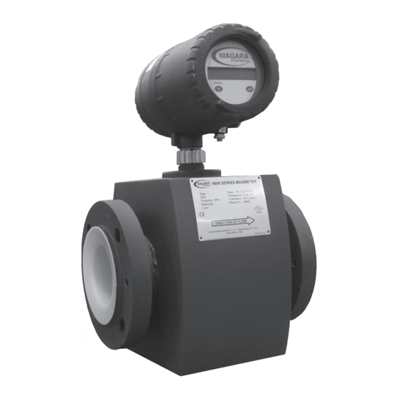
- Page 1 NIAGARA ® M600 meters Revision E October 2010 6600 Series Magnetic Flowmeter INSTALLATION, OPERATION & MAINTENANCE MANUAL...
-
Page 2: Using This Manual
USing ThiS ManUal This manual is designed to assist in installing, operating, and maintaining the 6600 Series Magnetic Flowmeter. SaFETY inFORMaTiOn Before installing the 6600 Series Magnetic Flowmeter, please read these instructions. Familiarize yourself with the requirements and functions. if any questions or problems arise please contact niagara Meters applications at 1-800-778-9242. -
Page 3: Table Of Contents
TaBlE OF COnTEnTS 1.0 PRODUCT DESCRIPTION PAGE Function Applications Principal of Operation Model Code Identification Technical Specifications Dimensions 2.0 HANDLING & STORAGE Inspection and Handling Storage 3.0 MECHANICAL INSTALLATION Guidelines Mounting 4.0 ELECTRICAL WIRING Guidelines Connection Information / Wiring Diagram 5.0 SET-UP & PROGRAMMING 6.0 MAINTENANCE 7.0 DIAGNOSTIC MESSAGES 8.0 TROUBLESHOOTING... -
Page 4: Product Description
1.0 PRODUCT DESCRiPTiOn 1.1 Function The 6600 Series is a low cost, Electromagnetic Flowmeter that combines ease of use and reliability to accommodate a wide range of applications. In the standard 6600 Series of Magnetic flowmeters, the SENSOR and the ELECTRONICS form one mechanical entity. -
Page 5: Applications
These meters offer an obstructionless, maintenance free alternative to mechanical flow devices. The 6600 series of electromagnetic flowmeters offer the user economical flow monitoring using pulsed DC technology. The design allows quick and easy installation without the need for skilled personnel and is virtually maintenance free. - Page 6 This equation holds true only when the pipe is completely filled, as we are assuming that the entire section of the pipe is always full. The measurement is not reliable if this condition is not fulfilled. Installation, Operation & Maintenance Manual M600 NIAGARA...
- Page 7 All program data is stored in NVRAM. Even in the case of power failure, programmed parameters are retained by the NVRAM. Data entry is accomplished by activating Hall Effect switches using a magnetic commander. Rev. E NIAGARA Installation, Operation & Maintenance Manual M600...
-
Page 8: Model Code Identification
Integral Remote (330ft max; specify cable length) Power 90VAC - 265VAC, 50/60 Hz If you require more than the standard 15ft cable, order part number 60524P010. Other materials of construction available, Consult Factory. Installation, Operation & Maintenance Manual M600 NIAGARA... -
Page 9: Technical Specifications
Agency Approvals FM3810 (General Purpose) for ½” to 24” FM3611 (Class 1 Div II, Group C&D) for ½” to 6” Protection IP 67 (1 meter immersion in water for 30 minutes) Rev. E NIAGARA Installation, Operation & Maintenance Manual M600... - Page 10 3” 59.52/27 92.59/42 4” 72.75/33 125.66/57 5” 99.2/45 6” 110.23/50 147.71/67 8” 121.25/55 176.37/80 10” 220.46/100 304.24/138 12” 286.6/130 405.65/184 357.15/162 511.47/232 429.9/195 623.9/283 18” 487.22/221 751.78/341 20” 694.46/315 1033.1/455 24” 826.73/375 1313.96/596 Installation, Operation & Maintenance Manual M600 NIAGARA...
- Page 11 20.00 155.50 1555.00 31100 25.984 28.465 28.465 694.46 24.00 220.00 2200.00 44900 31.102 32.992 32.992 826.73 20.00 155.50 1555.00 31100 25.984 28.465 28.465 694.46 24.00 220.00 2200.00 44900 31.102 32.992 32.992 826.73 Rev. E NIAGARA Installation, Operation & Maintenance Manual M600...
-
Page 12: Dimensions
1.6 Dimensional Drawing Installation, Operation & Maintenance Manual M600 NIAGARA... - Page 13 Rev. E NIAGARA Installation, Operation & Maintenance Manual M600...
- Page 14 Installation, Operation & Maintenance Manual M600 NIAGARA...
- Page 15 Rev. E NIAGARA Installation, Operation & Maintenance Manual M600...
- Page 16 3/4” BSP to 19.68/50 Separate Sensor CH 0.04 x 1.77/4x45 1.38/35 2.28/58 1. ALL DIMENSIONS ARE IN INCHES/MM UNLESS OTHERWISE SPECIFIED. 2. USE GENERAL TOLERANCES FOR OTHER THAN SPECIFIED. Installation, Operation & Maintenance Manual M600 NIAGARA...
- Page 17 Wall Mounting Plate assembly for housing Type C & D Extension Pipe O.D. 1.5/38, I.D. 1.26/32 MIG + CO2 Welding Bush for Mounting Plate 1.85/47 0.787/20 Mounting Plate 0.472/12 Rev. E NIAGARA Installation, Operation & Maintenance Manual M600...
-
Page 18: Handling & Storage
If you are using remote electronics, the electronic unit may be mounted up to 330 feet away depending on liquid conductivity. Installing the meter: There is a flow arrow on the meter housing. The meter should be installed so that the forward flow proceeds in the direction of the arrow. Installation, Operation & Maintenance Manual M600 NIAGARA... - Page 19 Do not lift the instrument with a fork lift as this could cause the casing to buckle and damage the internal coils. DIRECTION OF FLOW DIRECTION OF FLOW Rev. E NIAGARA Installation, Operation & Maintenance Manual M600...
-
Page 20: Storage
Only use the bolts and gaskets as described in the technical data of the operating manual b) Ensure the mains supply is switched off during installation. Install the flow meter at a location, such that the pipe is always full at that location Installation, Operation & Maintenance Manual M600 NIAGARA... - Page 21 The orientation of the flow meter should be such that the Empty Pipe Detection Electrode is always on the topside of the pipe, otherwise the Empty Pipe Detection function may not work. Rev. E NIAGARA Installation, Operation & Maintenance Manual M600...
-
Page 22: Mounting
12 - 0.875 x 4.5 150# 12 - 1 x 5 150# 16 - 1 x 5.25 150# 16 - 1.125 x 5.75 150# 20 - 1.125 x 6 150# 20 - 1.125 x 6.75 Installation, Operation & Maintenance Manual M600 NIAGARA... - Page 23 4 Bolts 8 Bolts Second Quadr ant Fi r s t Quadr ant Fi r s t Quadr ant Second Quadr ant 12 B o lts or M or e 8 Bolts Rev. E NIAGARA Installation, Operation & Maintenance Manual M600...
-
Page 24: Electrical Wiring
Relays are shown in De-energized condition. Maximum rating of relay is 2A at 230 V maximum for non-inductive load. Fuse is rated as T 1.0A, 250 VAC (slow blow). Care should be taken to ensure that no moisture or dust enters the housing. Installation, Operation & Maintenance Manual M600 NIAGARA... -
Page 25: Connection Information / Wiring Diagram
4.2 Connection information / Wiring Diagrams Cable Connection with Sensor (Remote) Rev. E NIAGARA Installation, Operation & Maintenance Manual M600... - Page 26 Teflon Wire TINNED WIRE 0.08/0.2 x 7 0.005/0.125 x 19 TEFLON SHEATHING 0.06/1.5 COPPER TIN COATED WIRE SHIELDING (0.04/0.12 x 0.16/4 x 0.63/16) TEFLON SHEATHING 0.09/2.5 NOTES: All dimensions are in inches/mm. Installation, Operation & Maintenance Manual M600 NIAGARA...
- Page 27 ~ 80% COVERING PVC SHEATHING .012/0.3 THK. NOMINAL COTTON THREAD ANNEALED TINNED PACKING COPPER WIRE BRAIDING PVC SHEATHING 0.37/9.5 + 0.04/1 0.02/0.5 THICK MAXIMUM RESISTANCE/KM: 58.7 Ohm Note: All dimensions are in inches/mm. Rev. E NIAGARA Installation, Operation & Maintenance Manual M600...
- Page 28 8 Relay Common position and J2 is in frequency position in meter. 9 Relay NO 10 Frequency/Pulse 11 Frequency/Pulse 12 Open Collector + 13 Open Collector COM 14 4-20 mA + 15 4-20 mA - Installation, Operation & Maintenance Manual M600 NIAGARA...
- Page 29 Rev. E NIAGARA Installation, Operation & Maintenance Manual M600...
- Page 30 Installation, Operation & Maintenance Manual M600 NIAGARA...
-
Page 31: Set-Up & Programming
An enable to the ENT key will show the options in the programming. It will start with the default option of the Bi-directional Mode. This message will display: Flow Measurement Bi-Directional Rev. E NIAGARA Installation, Operation & Maintenance Manual M600... - Page 32 An enable to the increment key will cause the programming to jump to the next parameter. An enable to the ENT key will activate the Unit for Program Mode and display the following message: Unit for Program CuM/hr Installation, Operation & Maintenance Manual M600 NIAGARA...
- Page 33 ENT key. Display Unit The option can be selected by enabling the increment key and accepted by an enable to the ENT key. Display Unit Rev. E NIAGARA Installation, Operation & Maintenance Manual M600...
- Page 34 No other option for Totalizer Units can be set for the Units for Program CuM/hr option. If Units for Program is GPM, the following message will display: Totalizer Units gals No other option for Totalizer Units can be set for the Units for Program GPM option. Installation, Operation & Maintenance Manual M600 NIAGARA...
- Page 35 An enable to the ENT key for this option will confirm the resetting of the Forward Totalizer. An enable to the increment key will ask for resetting of the Reverse (negative) Totalizer. An enable to the ENT will displaly the following message: are you sure? Reset Totalizer? Rev. E NIAGARA Installation, Operation & Maintenance Manual M600...
- Page 36 An enable to the ENT key will reset both the Forward and Reverse Totalizers and it will show the following display. An enable to the increment key will jump to the Reset Totalizers submenu. Resetting ... Totalizer ... After this submenu, the program will jump to the next parameter, Set Pulse On Time. Installation, Operation & Maintenance Manual M600 NIAGARA...
- Page 37 An enable to the increment key will display the previous value of the LO Alarm. If Unit for Program is CuM/hr, the following message will display: Enter lO alarm 10.00 CuM/hr Rev. E NIAGARA Installation, Operation & Maintenance Manual M600...
- Page 38 Relay 2 = LA Flow is the default parameter. This is the reset value for any subsequent attempt for programming of parameters. An enable of the ENT key will accept this configuration, while an enable of the increment key will show the following display: Relay Selection Relay 2 = EPD Installation, Operation & Maintenance Manual M600 NIAGARA...
- Page 39 Display Damp factor can be set from 1 to 9. An enable to the ENT key will accept the data and will move further to Exit the programming mode. EXiT After the programming of parameters is complete, the program will ask to exit. The following message will be displayed: EXiT? EnT To Exit Rev. E NIAGARA Installation, Operation & Maintenance Manual M600...
-
Page 40: Change Password
Instantaneous Flow Rate and Flow Totalizer value. The Flow Totalizer will remain stopped until the increment key is activated. The Flow Totalizer will restart after updating the value from the Flow Integrator, once the increment key is released. Installation, Operation & Maintenance Manual M600 NIAGARA... -
Page 41: Maintenance
5. Insert new fuse into base TR51A, 230 VAC. 6. Replace terminal PCB. Screw back into place ensuring it is tight. 7. Make all the connections. 8. Tighten the terminal cover. 9. Switch ON the instrument. Rev. E NIAGARA Installation, Operation & Maintenance Manual M600... -
Page 42: Diagnostic Messages
NOTE: 1. The display unit for flow rate will be according to set unit. 2. The Totalizer unit will be in CuM or Gal. Installation, Operation & Maintenance Manual M600 NIAGARA... -
Page 43: Troubleshooting
Poor readability of display 1. Viewing angle 1. Adjust viewing angle 2. Environmental brightness 2. Adjust contrast by trim pot provided just below display Relay output not available Incorrect of loose wiring Check wiring Rev. E NIAGARA Installation, Operation & Maintenance Manual M600... - Page 44 NIAGARA ® meters venture M EA SU R E M EN T 150 Venture Boulevard Spartanburg, SC 29306 Phone: (864) 574-8060, Fax: (864) 574-8063 Customer Care: (800) 778-9242 internet: http://www.niagarameters.com email: sales@niagarameters.com M600 Revision E © 2008 All rights reserved.
Need help?
Do you have a question about the 6600 Series and is the answer not in the manual?
Questions and answers