
Related Manuals for Chungho Iguassu CT II

Summary of Contents for Chungho Iguassu CT II
- Page 1 Technical & Repair guide for ChungHo Iguassu CT II IGUASSU CT II Technical Manual call 888.758.1234 for further technical support...
-
Page 2: Table Of Contents
Table of Contents 1. Designation of Components page 3 1-1. Front 1-2. Back 2. Product Features page 4-5 3. Exploded Diagram & Parts List page 6-7 4. System Diagram page 8 4-1. Water Purification Procedure 4-2. Cooling System Diagram 5. Distribution Line Diagram page 9 6. -
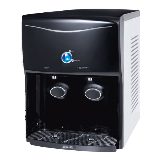
Page 3: Designation Of Components
Designation of Components 1-1 FRONT Hot Water Operation Display Water Full Display Hot Water Touch Sensor Button Cold Water Display Hot Water Display Ambient/Cold Water Touch Sensor Button Ambient Water Display Ambient/Cold Water Hot Water Dispensing Button Dispensing Button 1-2 BACK Hot Water ON/OFF Switch... -
Page 4: Product Features
Touch sensor application Breaking away from traditional button applications, the Iguassu CT II has a built- in touch sensor ap- plication. This addition has been integrated into the already stellar system with customer convenience in mind. The easy-to-use sensor application allows for effortless and enjoyable drinking water. - Page 5 Function operations are designed as simply as possible in order to maximize convenience. Environment friendly coolant The Iguassu CT II has adopted an environmentally friendly cooling system in the new R-134a, a cool- ant that will not add to the problems of ozone layer destruction and global warming.
-
Page 6: Exploded Diagram & Parts List
Exploded Diagram & Parts List EXPLODED DIAGRAM... - Page 7 PARTS LIST Cold water separator Drip Tray Rotation Cover sealing Rotation Cover Hot water ON Aircap Cover Water Full Hot water RUBBER-Dispensing btn. Dispensing button. Dispensing Button Cover Cold/Ambi water temp. select temp. select Tank Cover sealing Hot water dispensing Sol V/V dispensing Sol V/V Hot Dispense MPPE...
-
Page 8: System Diagram
냉정수기(CHP-2240D, 2241D) System Diagram ������ ������ �-������ �스� ��� �-������ �스� ��� CHP-2240D, 2241D 흐름도 * CHP-2240D는 자외선 살균기 없음 4-1. WATER PURIFICATION PROCEDURE Level Sensor Tank Solenoid Ambient Valve Water Tank Cold Ambient/Cold Water Tank Water Dispensing Ambient Water Sol. V/V Cold Water Sol. -
Page 9: Distribution Line Diagram
Distribution Line Diagram... -
Page 10: Product Specification
Product Specification... -
Page 11: Installation Precautions
Installation Precautions When installing the product, do not install it at the following places. - Near fire - Near flammable material - Wet place - A place exposed to rain and snow - A place exposed to direct sunshine - Near chemicals (volatile material, organic solvent, etc.) - A place below 32°F or a place with the possibility of dropping below 32°F Use the following water quality ramge. -
Page 12: Installation
Installation Install the product on a level surface. (Change product level using the product leg adjustment and confirm the level surface a level.) Close off the water supply valve as supplied to each household. Then tempo- rarily remove the connector part as provided from your given water source. Then connect the main water line adaptor. -
Page 13: Usage
Usage 9-1 SELECT / DESELECT FUNCTION Ambient / Cold Water Function There are no special setup or release functions on ambient and cold water operation. It operates auto- matically in terms of program controlled by PCB when the power supply is on. Hot Water Operation Setting If hot water operation display LED is turned on by setting the hot water operation switch to “ON”... -
Page 14: Operational Beep
9-2 WATER DISPENSING Ambient Water Dispense Mode Touch AMBI (ambient water dispensing selection) touch sensor button. (Light on GREEN on LED display) * If the ambient water LED (Green) is not turned on, the ambient water won’t come out even though the ambient water dispensing button is pressed. -
Page 15: System Formation
System Formation 10-1 FUNCTIONAL COMPONENTS Transformer & Sensors 1. Transformer : IN - AC220V/60Hz, OUT - AC21V/ 1.9A 2. Cold Water Sensor : NTC Type(PX-42H : 0°C 27.62 kΩ) 3. Hot Water Sensor : NTC Type(PT3-312 : 25°C 231.4 kΩ) 4. -
Page 16: Flow Restrictor
10-2 FLOW RESTRICTOR 1) Flow Restrictor Control Waste Water Amount (Alternated of AFV) 2) Position Located into the Membrane waste tubing line Caution 1. Disconnect Stem Elbow when replace membrane filter. (Do not separate tuning line with the Stem Elbow. 2. -
Page 17: System Malfunction Diagnosis & Repair Procedure
System Malfunction Diagnosis & Repair Procedure Table of Contents... - Page 18 11-1 POWER MALFUNCTION Symptom In case of LED display off although power connected. Detach top cover and right side cover, then find fuse holder. Check fuse inside the fuse holder if it is opened. > Replace fuse if it is faulty. Find transformer located at base plate of the unit then check its IN/OUT connection and voltage.
- Page 19 11-2 FILTRATION MALFUNCTION Check OLC and filtration process works properly. Check if there is water membrane on top of Mesh- OLC-S1 and medium filter area on the water tank. Check Membrane Check water supply valve is opened. Check wire connection of OLC and water level in the tube.
- Page 20 11-3 WATER DISPENSING (SOL V/V MALFUNCTION) Faulty water dispensing solenoid Valve (Hot/Cold/ Ambient) causes water dispensing malfunction. Check hot/cold/ambient water dispensing solenoid valves. - Check its voltage is DC24V supplies to Sol V/V at terminal when dispensing. > If not, replace Sol V/V - Check if there is leak of each Sol V/V.
- Page 21 11-4 HOT WATER MALFUNCTION If hot water overheated, ambient tank’s temperature goes up then it could causes overflow. Check electric resistance of hot water temp-sensor and manual bimetal. Hot water temp-sensor : Check electric resistance. (Refer page 25) Manual Bimetal : 105N (Off when 105°C) Check if hot temp-sensor is affixed properly onto hot water tank’s surface.
- Page 22 11-5 DISPLAY AND TOUCH BUTTON MALFUNCTION LED display and touch sensor button work abnor- mally. Check touch sensor PCB’s wire connection. Touch sensor PCB - Check wire & terminal connection - Check if sponge is squeezed. - Check if PCB moisten...
- Page 23 11-6 MALFUNCTION BY COOLANT’S LEAK OR CLOGGING If malfunction causes by leak or clogging of coolant. > Send to ChungHo Repair Center Coolant leak could be happened at welding area. It can be gauged below 60W power consumption by using power meter device.
- Page 24 11-7 SENSOR & SWITCH...
- Page 25 11-8 COLD WATER SENSOR TEMPERATURE TABLE (°F) (KΩ) (°F) (KΩ) (°F) (KΩ) 116.8 22.3 90.1 18.1 14.7 54.9 12.1 43.4 34.5 27.6 11-9 HOT WATER SENSOR TEMPERATURE TABLE (°F) (KΩ) (°F) (KΩ) (°F) (KΩ) 806.4 147.3 36.2 618.9 118.6 30.2 478.7 96.1 25.3...
-
Page 26: System Disassembling
Disassembling Top Cover - Press and hold front of top cover and push forward. Front Panel - Unscrew each top corner screws at the back of the front panel.(2 pieces) Front Panel - Extract drip tray. Front Panel - Unscrew each side at the front bottom of front panel. - Page 27 Front Panel – Press and hold each top side from up to down direction then pull out. Front Panel - Disconnect wire connection of touch sensor PCB. Back Panel – Unscrew 6 pieces of back panel screws. Side Panel – Slide side panels from front of unit to the back.
-
Page 28: Filter Changing
Filter Change Sediment Filter Pull Sediment filter then disconnect tubing line. Pre-Carbon Filter Pull Pre-Carbon filter then disconnect tubing line. R/O Membrane Filter Pull Membrane filter then disconnect tubing line. Refer page 16 to disconnect waste water tubing line. Post-Carbon Filter Pull Post-Carbon filter then disconnect tubing line. -
Page 29: Water Draining
Water Draining Hot Water Pull Pre-Carbon filter and connect drain hose into drain connector then drain water. Drip Hose Drain Connector Cold/Ambient Water Same as dispensing (Refer page 14) Drip Tray Remove water before full. -
Page 30: Tank Cleaning
Tank Cleaning Ambient Tank Extract (Revolve and pull) top round cover then clean inside the tank. Ambient Tank Push locking clips (7EA) to unlock (open) position then extract top cover of water tank. Ambient Tank Extract cold water tank panel then clean. -
Page 31: Parts Replacing
Parts Replacing Table of Contents Malfunction Page Controller Touch Sensor PCB Hot Water Sensor & Manual Bimetal Hot Water Tank Cold Water Sensor Inlet Solenoid Valve Water Dispensing Solenoid Valve Pump Transformer & Fuse Power Cord Stabilizer PCB OLC-S1... -
Page 32: Controller
17-1 CONTROLLER Extract bottom screw. Press both side of controller cover top to extract. Disconnect all connected wires then extract 4 screws each corner. Replace controller. -
Page 33: Touch Sensor Pcb
17-2 TOUCH SENSOR PCB Remove 4 screws on Faucet Deco, extract the faucet Deco then remove 3 screws on the PCB cover. Extract PCB cover then remove screw on the middle of PCB. Push PCB holding Hook(6EA) and extract. Replace touch sensor PCB. -
Page 34: Hot Water Sensor & Manual Bimetal
17-3 HOT WATER SENSOR & MANUAL BIMETAL Remove bottom screw on the controller cover then press both side of controller cover top to extract. Disconnect hot water sensor terminal connected. to controller. Extract hot water sensor BKT & manual bimetal. Replace sensor &... -
Page 35: Hot Water Tank
17-4 HOT WATER TANK Disconnect hot water sensor terminal connected to controller. Extract bimetal and disconnect hot water heater terminal. Disconnect 4 silicone tubes connected to hot water tank. Extract 2 butterfly shaped nuts holding hot water tank. Replace hot water tank. -
Page 36: Cold Water Sensor
17-5 COLD WATER SENSOR Disconnect cold water sensor terminal on the controller. Extract insulating material. Extract lagging material then remove 2 cold water sensor holding screws. Replace cold water sensor. -
Page 37: Inlet Solenoid Valve
17-6 INLET SOLENOID VALVE Separate Pre-Carbon filter. Disconnect inlet Sol V/V connector. Remove 3 of inlet Sol V/V holding screws then disconnect tubing line connected to the valve. Replace inlet Sol V/V. -
Page 38: Water Dispensing Solenoid Valve
17-7 WATER DISPENSING SOLENOID VALVE Unplug terminal of the dispensing Sol V/V. Extract silicone tube of the dispensing Sol V/V. Remove the dispensing Sol V/V holding screw(s) and the connected silicone tube. Replace the water dispensing solenoid valve. * When assemble silicone tube on No.2, must maintain silicone tube vertically and make sure Mesh not to be squeezed. (It causes faulty dispensing Sol V/V) -
Page 39: Pump
17-8 BOOSTER PUMP Remove 2 pump holding screws underneath of base plate. Disconnect terminal connected to pump and re- move 2 pump holding screws on the base plate. Pull pump towards upper front to extract. Replace booster pump. -
Page 40: Transformer & Fuse
17-9 TRANSFORMER & FUSE Unscrew wire holding retainer then disconnect transformer terminal. Remove transformer holding screw. Push both side of fuse holder then turn to the left to loosen. Replace transformer/fuse. -
Page 41: Power Cord
17-10 POWER CORD - Extract both side panels. - Remove 4 pieces of rear cover holding screws. - Remove wire condenser holding screw. Pull up ambient tank then separate rear cover. Disconnect hot water ON/OFF switch then extract rear cover. Remove power cord terminal and holding screw. -
Page 42: Stabilizer Pcb
17-11 STABILIZER PCB - Extract left side panel. - Remove stabilizer PCB cover holding screws (2 pieces). Disconnect stabilizer PCB terminal then remove 2 pieces of PCB holding screws. Replace stabilizer PCB. -
Page 43: Olc-S1
17-12 OLC-S1 Disconnect OLC-S1 terminal on controller. Separate Sediment filter. Remove 2 pieces of OLC-S1 holding screws then extract silicone tube. Replace OLC-S1. - Page 44 ChungHo USA 16590 Aston St. Irvine CA 92606 888.758.1234 www.chunghousa.com techsupport@chunghousa.com...
Need help?
Do you have a question about the Iguassu CT II and is the answer not in the manual?
Questions and answers