Advertisement
Quick Links
Advertisement

Related Manuals for Micanan Pro-APTC


Summary of Contents for Micanan Pro-APTC
- Page 1 Serial #: Installation Date: Wiring Diagram: PRO-APTC...
- Page 2 POWER DURING INSTALLATION OR SERVICING OF OPERATOR IMPORTANT FOR ANY QUESTIONS CONCERNING THE SAFETY OR OPERATION OF THIS OPERATOR PLEASE CONTACT For more information, please visit www.devancocanada.com MICANAN SYSTEMS AT 1-877-888-1116 SAVE THESE INSTRUCTIONS or call toll free at 855-931-3334...
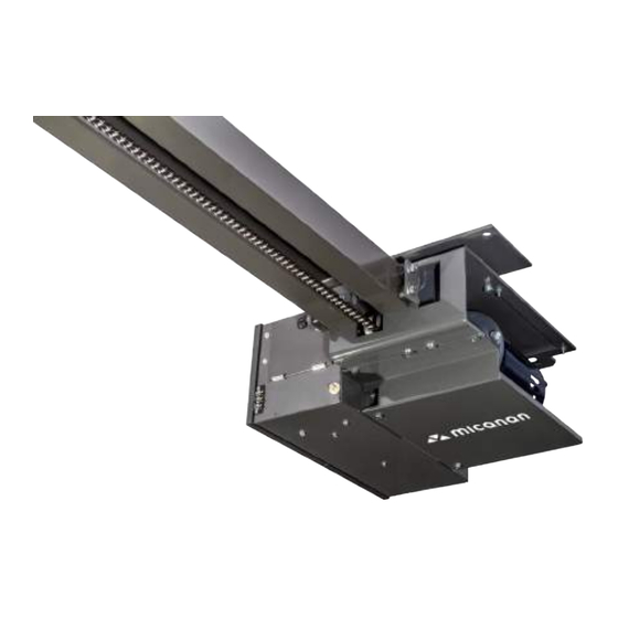
- Page 3 VERIFICATION OF OPERATOR AND HARDWARE Upon delivery of your MICANAN SYSTEMS heavy-duty apartment/condo trolley door operator, please inspect the unit carefully for damage. Verify that operator horsepower, voltage, phase and amperage correspond to available power supply and door application. The operator is shipped with rails, drive chain, carriage and the straight-bar of the trolley arm already assembled.
- Page 4 PRO-APTC SPECIFICATIONS PRO-APTC heavy-duty apartment/condo trolley operators are designed for standard lift overhead sectional garage doors. Model PRO-APTCB is essentially the same as model PRO-APTC with the exception that the PRO-APTCB operator has an electric braking system. STANDARD OPERATOR WEIGHT: Operator/rail assembly: 150 Lbs MOTOR: •...
- Page 5 IMPORTANT SAFETY INSTRUCTIONS WARNING TO REDUCE THE RISK OF INJURY OR DEATH: - READ AND FOLLOW ALL INSTRUCTIONS - Never allow children to operate or play with door controls. Keep the remote control (where provided) away from children. - Personnel should keep away from a door in motion and keep the moving door in sight until it is completely closed or opened.
- Page 6 INSTALLATION INSTRUCTIONS WARNING DO NOT INSTALL THIS OPERATOR BEFORE READING THIS MANUAL CAREFULLY. Note: Installation of operator must be done by a qualified installer. Door must be properly installed and working smoothly. Remove all door locks prior to installation. 1. Install control station away from all moving door parts, within sight of the door and a minimum of 5 ft (1.5 m) from the ground.
- Page 7 WALL MOUNTING BRACKET AND OPERATOR INSTALLATION: NOTE: Trolley type operators should generally be mounted directly over the center of the door and the trolley rails should clear the tracks by 2-1/2” (6.5 cm). However, if interfering structures or other reasons do not allow for centered mounting, it is possible to install it up to 18”...
- Page 8 6. If required, mount a wood block or angle iron to the wall above the door opening (Fig D). 7. Flip operator assembly so that carriage/trolley are facing the ground. While allowing motor side to rest on floor, lift rail assembly side of operator above door and align according to previously identified centerlines (Fig E).
- Page 9 10. For high ceiling applications, install hanging brackets (braces) from ceiling or structure to operator mounting plate. TROLLEY ARM INSTALLATION: 1. With door closed and trolley carriage positioned close to end of rails. align the mounting holes of straight arm and curved arm so that pivot bolt on door bracket is in line with the top rollers of the door.
- Page 10 IMPORTANT - EACH INDIVIDUAL COMMERCIAL DOOR OPERATOR MUST HAVE IT’S OWN DEDICATED POWER SUPPLY - MICANAN HIGHLY RECOMMENDS THAT EACH INDIVIDUAL COMMERCIAL DOOR OPERATOR HAVE AN EXTERNAL CIRCUIT BREAKER OR FUSED DISCONNECT WARNING COMPARE AVAILABLE POWER SUPPLY VOLTAGE TO OPERATOR NAMEPLATE PRIOR TO ELECTRICAL CONNECTION.
- Page 11 SECTION A: PRO-APTC(E), Full feature logic board Smart 10.0 with auxiliary apt board (UL325 compliant) Note: The operator is shipped from the factory in the D1 mode setting (constant pressure open and close). The operator should remain in this mode until all connections and limit switch adjustments are completed.
- Page 12 1 or more secondary non-monitored safety device(s). PRIMARY MONITORED SAFETY DEVICE: MICANAN compatible monitored failsafe photocells or MICANAN compatible monitored failsafe devices must be connected to terminals P1 and P2 as primary monitored safety device. Primary monitored safety device must be connected if momentary activation on close is required in B2, T and TS modes.
- Page 13 Secondary non-monitored safety device(s): A standard 2-wire safety edge, non-monitored photocells or any other non-monitored reversing devices with a N.O contact can be connected to terminals S1 and S2 as secondary non-monitored safety device. Note: More than one secondary non-monitored safety device can be connected to terminals S1 and S2. Important: Do not remove the resistor that is factory installed across terminals S1 and S2 unless installing a 4-wire electric edge.
- Page 14 C2 (Momentary open, constant pressure close) • Open Button: Momentary activation opens the door. When door is closing, momentary activation reverses the door (OPEN OVERRIDE). Momentary contact from mid-stop opens the door to full open position. Constant activation when door is opening, bypass mid-stop if enabled.
- Page 15 • Timer to close: Closes the door from mid-stop or full open. Momentary activation of stop button will de-activate the timer. When door is closing, momentary activation of safety devices will reverse the door to mid-stop (if enabled) or full open and de-activates the timer.
- Page 16 POT2 amount of time. ON-BOARD RECEIVER PROGRAMMING This logic board has a built-in 372 MHz radio receiver and can only be used with MICANAN single button, 3-button (OPEN/CLOSE/STOP) and 3-channel radio transmitters. INSTALLING THE ANTENNA Direct Connection: Attach the antenna when supplied with the operator to the F connector on the control box.
- Page 17 • Dry contact for door full close status: Contact closes when door is fully closed. MICANAN recommends the following setup and traffic light sequence in a typical apartment/condo installation: • Mode of operation : TS (Set timer to close dial to desired value) •...
- Page 18 (1) this device may not cause harmful interference, and (2) this device must accept any interference received, including interference that may cause undesired operation. Note: If an external radio-receiver (MICANAN or other) is used instead of the built-in radio receiver, it is highly recommended to disconnect the co-axial cable from the logic board.
- Page 19 Delay on reverse Delay on reverse is 1.5 seconds Delay on reverse is 0.5 seconds Micanan recommends 1.5 sec delay on reverse for all applica- tions Motor direction Reverse motor direction...
- Page 20 SECTION B: For all operator control types LIMIT SWITCH ADJUSTMENT Adjustment of door travel is done by moving the limit cams on the threaded shaft. The position of the 4 limit switches are factory adjusted and should not be altered. The limit switches are: - “Open”...
- Page 21 IMPORTANT: For momentary activation on close, the MICANAN photocells (or a Micanan 2-wire monitored edge), must be installed as part of the operator system. If a Micanan 2-wire monitored edge or the MICANAN infrared photocells system is not installed (or not operating correctly), the operator will only operate in fault mode (constant pressure to close).
- Page 22 When the photo system is properly installed and aligned, the infrared beam will detect any obstruction in the path of the beam. Upon detecting an obstruction, closing door will stop and reverse to full open. The MICANAN operator control circuit continuously monitors the correct operation of the photo system.
- Page 23 FRABA N-4/4X THRU-BEAM PHOTOCELL (MK00697) Note: The MK00697 photocell system has a maximum range of 45 ft. Sun visor protector optional. 3. Select a location on the wall no more than 6 inches from the floor to install wall mounting brackets on the left and right side of the door.
- Page 24 EMERGENCY MANUAL OPERATION - The operator is equipped with a dual handle quick release disconnect system to manually operate door in case of emergency. This feature should not be used to manually operate a malfunctioning door. WARNING TO REDUCE THE RISK OF INJURY OR DEATH: DO NOT ATTEMPT TO USE EMERGENCY DISCONNECT SYSTEM WHILE OPERA- TOR IS RUNNING.
- Page 25 25 25 OPERATOR MAINTENANCE WARNING TO REDUCE THE RISK OF INJURY OR DEATH: DO NOT ATTEMPT TO SERVICE THE OPERATOR UNLESS POWER SUPPLY HAS BEEN DISCONNECTED - Inspect manual function of the door every 3-months. Make sure that door runs smoothly. If door does not manually open or close freely, have a qualified service person make repairs.
- Page 26 � 05.05.15 I c.s. D.J. MKCANAN §Y§IBM§ lINC. DATE: I APPROVED: I DRAWN BY: TITLE UNLESS OTHERWISE SPECIFIED JPRO-APrC DIMENSIONS ARE IN INCHES TOLERANCES .XX=±,01 ANGLES=±30' MATERIAL \./EIGHT SIZE RIBVJI§][ON:A CAD FILE: PRD-APTC-XE ISCALE: 1:4IPAGE 1/11...
- Page 28 MICANAN Commercial Door Opening Devices...
- Page 29 MICANAN Commercial Door Opening Devices...
- Page 30 MICANAN Commercial Door Opening Devices...
- Page 31 Notes...
- Page 32 HOW TO ORDER REPAIR PARTS DEVANCO CANADA 19192 HAY ROAD, UNIT Q SUMMERSTOWN, ON K0C 2E0 TOLL FREE: 855-931-3334 www.devancocanada.com WHEN ORDERING REPAIR PARTS PLEASE SUPPLY THE FOLLOWING INFORMATION: 3 PART NUMBER 3 DESCRIPTION 3 MODEL NUMBER...
Need help?
Do you have a question about the Pro-APTC and is the answer not in the manual?
Questions and answers