
Summary of Contents for AUTIC APPC-8429T
-
Page 1: Installation And User Manual
AUTIC SYSTEM MARINE PC INSTALLATION AND USER MANUAL Autic System Marine PC Rev. 1.3 Jan 2017... - Page 2 Claims for errors or omissions with the item must be carried out without undue delay. Autic System AS liability is limited to repair or replacement of the products. Autic System AS is not responsible for replacement costs or other consequential damages.
-
Page 3: Table Of Contents
CONTENTS Contents................................3 About the Autic Marine PC Product Series ....................... 6 Autic Panel PC ..............................6 Range of Panel PC products ..........................7 Product Identification ............................7 Specifications Panel PC ............................8 Technical Data ..............................8 Supported Operating Systems ........................8 Motherboard Specification .......................... - Page 4 Using the Box/Mini PC ............................29 On-Off and Reset Buttons ..........................29 Remote On-Off Switch ..........................29 Restore on AC/Power Loss ..........................29 Autic Marine Monitors ........................... 30 Range of Products ............................. 31 Product Identification ............................31 Specification Monitors ............................32 Technical Data ...............................
- Page 5 Customer Specified or Trial Version ........................59 Shutting Down Properly ............................ 59 Declaration of Conformity for LCD Display ..................... 60 Service ................................61 Return of products to Autic System........................61 Accessories ................................ 62 Autic System Marine PC Rev. 1.1...
-
Page 6: About The Autic Marine Pc Product Series
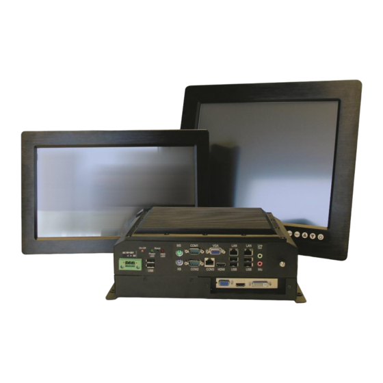
Membrane keypad for monitor adjustment The APPC series is Panel PCs designed for Autic System for optimal solution of HMI functionality to marine and industrial markets. Fanless design with solid aluminium front bezel. Powerful CPU based on Intel Bay Trail N2930 quad Core processor provides maximum performance based on known platform. -
Page 7: Range Of Panel Pc Products
16.7M 4 + 2 70 W PRODUCT IDENTIFICATION Product description: APPC-2429T-MK-8N APPC Product family name (Autic Panel PC) Size of display Motherboard Id. (Intel 2930) Touch screen Membrane keypad for monitor adjustment. Located at the front bezel. 8N/10N Sun readable. LED backlight (800 / 1000 nit) -
Page 8: Specifications Panel Pc
Marine certification DNV 2.4 and IEC60945 SUPPORTED OPERATING SYSTEMS The CPU supports Windows 7, 8 and 10 operating system. Linux Kubuntu. Ask for other Linux versions. It does not support Windows XP. Autic System Marine PC Rev. 1.1 Page 8... -
Page 9: Motherboard Specification
SATA2 (3.0Gb/s) Transfer Rate Rear I/O HDMI DisplayPort Ethernet 4 (2 x USB 3.0, 2 x USB 2.0) Audio 2 (Mic-in, Line-out) Serial 3 (RS232/422/485) PS/2 2 (1 x keyboard, 1 x mouse) Autic System Marine PC Rev. 1.1 Page 9... - Page 10 PWR 9-19V DC-In (4-pin ATX PWR Con) Power On AT/ATX Supported -AT : Directly PWR on as power input ready -ATX : Press button to PWR on after power input ready Environment Temperature 0ºC – 60ºC Autic System Marine PC Rev. 1.1 Page 10...
-
Page 11: Panel Pc Connectors
ON/OFF and Reset button Dual 9-32VDC Power Remote ON/OFF PCIe x1 Slot 2xUSB Ground COM port* terminal I/O Panel *The number of serial ports depend on the size of the Panel PC. Autic System Marine PC Rev. 1.1 Page 11... -
Page 12: I/O Panel
RTX- RTX+ COM1: COM1: COM1: +5V/+12V/+5VSB +5V/+12V/+5VSB +5V/+12V/+5VSB COM2, 3: +5V/+12V COM2, 3: +5V/+12V COM2, 3: +5V/+12V When setting COM 1~3 to RS-485 in BIOS, also enable Auto Flow Control if applicable. Autic System Marine PC Rev. 1.1 Page 12... -
Page 13: Ethernet
100Mbps Link Green 1Gbps USB Pin Configuration The Panel PC has galvanic isolation against the 24 VDC feed. There is no galvanic isolation between the communication ports for RS-232, RS-422/485 and USB. Autic System Marine PC Rev. 1.1 Page 13... -
Page 14: Installing The Panel Pc
COMPASS SAFETY DISTANCE The Panel PC is certified according to DNV 2.4 and IEC60945 for bridge installation. Standard compass safe distance: 95 cm Steering compass safe distance: 65 cm Autic System Marine PC Rev. 1.1 Page 14... -
Page 15: Installation Methods
4 screws through holes in the front bezel (OPTIONAL). Suitable when there is no access from rear. Prepared for VESA standard bracket at rear side. Various sizes according to size of Panel PC. Fastening holes in monitor back plate. Autic System Marine PC Rev. 1.1 Page 15... -
Page 16: Electrical Installation
6) After power on, make sure that the system performs a normal startup of the OS. 7) The system may be delivered with a 30 day trial version of Windows OS. Make sure you have a valid Autic System Marine PC Rev. 1.1... -
Page 17: Using The Panel Pc
When Panel PC is on. Single touch/pulse will stop the unit. RESTORE ON AC/POWER LOSS The Restore on AC/Power loss is hard coded to “Power On”. Regardless of the value set in BIOS, the PC powers on when the AC/power is restored. Autic System Marine PC Rev. 1.1 Page 17... -
Page 18: Monitor Adjustment, Models With High Brightness
This is due to the number of dimming levels. 3. For models with a serial number prior to 1608004-A (manufactured before Aug 2016): - After pushing Fully Dark, use Night Mode, Day Mode or + to bring light back. Autic System Marine PC Rev. 1.1 Page 18... -
Page 19: Autic Box Pc
Trail N2930 quad Core processor provides maximum performance based on known platform. Intel® Gen7 Intel® Graphics DX 11 for quick screen refresh. The PC is delivered with practical functionality such as easy access to the hard drive and redundant power supply connectors. Autic System Marine PC Rev. 1.1 Page 19... -
Page 20: Range Of Box Pc Products
4 + 2 25 W The number of LAN and serial ports can be increased on request. PRODUCT IDENTIFICATION Product description: AMPC-2930 AMPC Product family name (Autic Mini PC) 2930 Motherboard Id. (Intel 2930) Serial number: A2930-SSD120G-HS-DC-1604022-A SSD120G 120GB SSD... -
Page 21: Technical Data
Marine certification DNV 2.4 and IEC60945 SUPPORTED OPERATING SYSTEMS The CPU supports Windows 7, 8 and 10 operating system. Linux Kubuntu. Ask for other Linux versions. It does not support Windows XP. Autic System Marine PC Rev. 1.1 Page 21... -
Page 22: Motherboard Specification
SATA2 (3.0Gb/s) Transfer Rate Rear I/O HDMI DisplayPort Ethernet 4 (2 x USB 3.0, 2 x USB 2.0) Audio 2 (Mic-in, Line-out) Serial 3 (RS232/422/485) PS/2 2 (1 x keyboard, 1 x mouse) Autic System Marine PC Rev. 1.1 Page 22... - Page 23 PWR 9-19V DC-In (4-pin ATX PWR Con) Power On AT/ATX Supported -AT : Directly PWR on as power input ready -ATX : Press button to PWR on after power input ready Environment Temperature 0ºC – 60ºC Autic System Marine PC Rev. 1.1 Page 23...
-
Page 24: Box Pc Connectors
BOX PC CONNECTORS 2xCOM 2xUSB ON/OFF and Reset button Grounding terminal Dual 9-32VDC Power PCIe x1 slot I/O Panel Remote ON/OFF Bracket for cable strain relief Autic System Marine PC Rev. 1.1 Page 24... -
Page 25: I/O Panel
RTX- RTX+ COM1: COM1: COM1: +5V/+12V/+5VSB +5V/+12V/+5VSB +5V/+12V/+5VSB COM2, 3: +5V/+12V COM2, 3: +5V/+12V COM2, 3: +5V/+12V When setting COM 1~3 to RS-485 in BIOS, also enable Auto Flow Control if applicable. Autic System Marine PC Rev. 1.1 Page 25... -
Page 26: Ethernet
100Mbps Link Green 1Gbps USB Pin Configuration The Panel PC has galvanic isolation against the 24 VDC feed. There is no galvanic isolation between the communication ports for RS-232, RS-422/485 and USB. Autic System Marine PC Rev. 1.1 Page 26... -
Page 27: Installing The Box/Mini Pc
INSTALLATION OPTIONS IMPORTANT! Please observe that by installing any parts not supplied by Autic, such as additional memory modules or HDDs, you will do so at your own risk, and the warranty of the product will no longer be valid. -
Page 28: Electrical Installation
5) After power on, make sure that the system performs a normal startup of the OS. 6) The system may be delivered with a 30-day trial version of Windows OS. Make sure you have a valid Autic System Marine PC Rev. 1.1... -
Page 29: Using The Box/Mini Pc
When Box PC is on. Single touch/pulse will stop the unit. RESTORE ON AC/POWER LOSS The Restore on AC/Power loss is hard coded to “Power On”. Regardless of the value set in BIOS, the PC powers on when the AC/power is restored. Autic System Marine PC Rev. 1.1 Page 29... -
Page 30: Autic Marine Monitors
Membrane keypad for monitor adjustment AMON is a series of monitors designed for Autic System for optimal solution of HMI functionality to marine and industrial markets. Monitors are delivered with practical functionality such as redundant power connections. Autic System Marine PC Rev. -
Page 31: Range Of Products
1920x1080 300 nit LED 16.7M 55 W PRODUCT IDENTIFICATION Product description: AMON-240T-AL-8N AMON Product family name (Autic Monitor) Size of display, (24”) Resistive Touch Screen Aluminium front bezel 8N/10N Sun Readable. LED backlight (800 / 1000 nit) Serial number: AM236T-AMK-8N-1604022-C... -
Page 32: Specification Monitors
Ambient temperature. Vertical mounting 0° to +60°C Ambient temperature. Horizontal mounting 0° to +50°C Storage temperature -20° to +80°C Relative humidity 5 - 85% non-condensing Approvals CE/ FCC/Rohs Marine certification DNV 2.4 and IEC60945 Autic System Marine PC Rev. 1.1 Page 32... -
Page 33: Monitor Connectors
MONITOR CONNECTORS Example drawing. Variation due to Model ON/OFF button (on membrane keypad) Ground Dual 9-32VDC Audio input terminal Power USB for Touch USB Pin Configuration Autic System Marine PC Rev. 1.1 Page 33... -
Page 34: Installing The Monitor
COMPASS SAFETY DISTANCE The monitor is certified according to DNV 2.4 and IEC60945 for bridge installation. Standard compass safe distance: 100 cm Steering compass safe distance: 70 cm Autic System Marine PC Rev. 1.1 Page 34... -
Page 35: Installation Methods
4 screws through holes in the front bezel. Suitable when there is no access from rear. This mounting is optional. Prepared for VESA standard bracket at rear side. Various sizes according to size of monitor. Autic System Marine PC Rev. 1.1 Page 35... -
Page 36: Electrical Installation
3) Ground the unit according to installation instruction. 4) Make sure the polarity is correct for power connection before connecting to power outlet. 5) Keep signal cable and high voltage cable separated. Autic System Marine PC Rev. 1.1 Page 36... -
Page 37: Using The Monitor
2) Under menu, AUTO key functions as "exit" to leave the menu. ON/OFF Switch the monitor off/on. Note that the monitor ON/OFF function can be disabled from factory. This must be specified when ordering the monitor. Autic System Marine PC Rev. 1.1 Page 37... -
Page 38: Monitor Adjustments (Old Version)
Brightness for this display is not dimmable down to 1 nit as specified in IEC 60945 for use on bridge. Switch off the standard-brightness monitor. Note that the monitor ON/OFF function can be disabled from factory. This must be specified when ordering the monitor. Autic System Marine PC Rev. 1.1 Page 38... -
Page 39: Product Dimensions
APPC-1229T 5 kg APPC-1229T 5 kg APPC-1529PT 6 kg APPC-1729PT 7 kg APPC-1929PT 8 kg 16:9 models APPC-11629T 5 kg APPC-15629T 6 kg APPC-18529T 9 kg APPC-2229T 9 kg APPC-2429T 10 kg Autic System Marine PC Rev. 1.1 Page 39... -
Page 40: Panel Pc 4:3 Models
PANEL PC 4:3 MODELS APPC-8429T APPC-1029T Autic System Marine PC Rev. 1.1 Page 40... - Page 41 APPC-10429T-XGA APPC-1229T Autic System Marine PC Rev. 1.1 Page 41...
- Page 42 APPC-1529T APPC-1727T Autic System Marine PC Rev. 1.1 Page 42...
-
Page 43: Panel Pc 16:9 Models
APPC-1929T PANEL PC 16:9 MODELS APPC-11629T Autic System Marine PC Rev. 1.1 Page 43... - Page 44 APPC-15629T APPC-1829T APPC-2229T Autic System Marine PC Rev. 1.1 Page 44...
-
Page 45: Box/Mini Pc Dimension
APPC-2429T BOX/MINI PC DIMENSION AMPC-2930 Autic System Marine PC Rev. 1.1 Page 45... -
Page 46: Monitor Dimensions
AMON-104T-AL-XGA 3 kg AMON-120T-AL 4 kg AMON-150T-AL 5 kg AMON-170T-AL 6 kg AMON-190T-AL 8 kg 16:9 models AMON-116T-AL 4 kg AMON-156T-AL 6 kg AMON-185T-AL 8 kg AMON-220T-AL 8.5 kg AMON-240T-AL 9.5 kg Autic System Marine PC Rev. 1.1 Page 46... -
Page 47: Uefi And Bios Settings
Use ← or → to choose among the selections on the menu bar, and then press <Enter> to get into the sub screen. You can also use the mouse to click your required item. Autic System Marine PC Rev. 1.1... -
Page 48: Navigation Keys
Print screen <ESC> To jump to the Exit Screen or exit the current screen MAIN SCREEN When you enter the UEFI SETUP UTILITY, the Main screen will appear and display the system overview. Autic System Marine PC Rev. 1.1 Page 48... -
Page 49: Advanced Screen
If you execute Instant Flash utility, the utility will show the UEFI files and their respective information. Select the proper UEFI file to update your UEFI, and reboot your system after UEFI update process completes. Autic System Marine PC Rev. 1.1... -
Page 50: Cpu Configuration
When this option is set to [Enabled], a VMM (Virtual Machine Architecture) can utilize the additional hardware capabilities provided by Vanderpool Technology. This option will be hidden if the installed CPU does not support Intel Virtualization Technology. Autic System Marine PC Rev. 1.1 Page 50... -
Page 51: Chipset Coniguration
PCIE1 LINK SPEED Select the link speed for PCIE1. DEEP S5 Mobile platforms support Deep S5 in DC only and desktop platforms support Deep S5 in AC only. The default value is [Disabled]. Autic System Marine PC Rev. 1.1 Page 51... -
Page 52: Storage Configuration
Use this item to configure SATA Aggressive Link Power Management. HARD DISK S.M.A.R.T. Use this item to enable or disable the S.M.A.R.T. (Self-Monitoring, Analysis, and Reporting Technology) feature. Configuration options: [Disabled] and [Enabled]. Autic System Marine PC Rev. 1.1 Page 52... -
Page 53: Intel® Smart Connect Technology
Use this to set parameters of COM3. Select COM3 port type: [RS232], [RS422] or [RS485]. COM4 / COM 6 CONFIGURATION Use this to set parameters of COM4 and COM 6. [Enabled] or [Disabled] LPT1 PORT CONFIGURATION Use this set parameters of the onboard parallel port. Autic System Marine PC Rev. 1.1 Page 53... -
Page 54: Acpi Configuration
Use this item to enable or disable USB Keyboard/Remote to power on the system. USB MOUSE POWER ON Use this item to enable or disable USB Mouse to power on the system. Autic System Marine PC Rev. 1.1 Page 54... -
Page 55: Usb Coniguration
CPU temperature, motherboard temperature, CPU fan speed, chassis fan speed, and the critical voltage. CPU_FAN1 SETTING This allows you to set CPU_FAN1’s speed. Configuration options: [Full On] and [Automatic Mode]. The default value is [Full On]. Autic System Marine PC Rev. 1.1 Page 55... -
Page 56: Cha_Fan1 Setting
Set or change the password for the user account. Users are unable to change the settings in the UEFI Setup Utility. Leave it blank and press enter to remove the password. SECURE BOOT Enable to support Windows 8 64-bit Secure Boot. Autic System Marine PC Rev. 1.1 Page 56... -
Page 57: Boot Screen
Select whether the Boot Beep should be turned on or off when the system boots up. Please note that a buzzer is needed. FULL SCREEN LOGO Use this item to enable or disable OEM Logo. The default value is [Enabled]. Autic System Marine PC Rev. 1.1 Page 57... -
Page 58: Csm (Compatibility Support Module)
When you select this option, it will pop-out the following message, “Discard changes?” Select [OK] to discard all changes. LOAD UEFI DEFAULTS Load UEFI default values for all the setup questions. F9 key can be used for this operation. Autic System Marine PC Rev. 1.1 Page 58... -
Page 59: Launch Efi Shell From Filesystem Device
Shut down the computer in a proper way. If not, the operating system or application software may get interrupted and lose data. Do not switch the power supplies off to shut down the computer, follow the proper shut-down procedure from the operating system. Autic System Marine PC Rev. 1.1 Page 59... -
Page 60: Declaration Of Conformity For Lcd Display
DECLARATION OF CONFORMITY FOR LCD DISPLAY Autic System declare that their LCD panels are conformed with the standard ISO 13406-3 (Class 3). “The standard lists four classes of devices, where a device of a specified class may contain a certain maximum number of defective pixels. The table below shows the maximum number of allowed defects (per type) per 1 million pixels. -
Page 61: Service
SERVICE All service for these products must be done by Autic System AS. RETURN OF PRODUCTS TO AUTIC SYSTEM. Return equipment for service by registering the products via RMA registration at www.autic.no / Support / Returskjema (Return Form). Autic System Marine PC Rev. -
Page 62: Accessories
Specify product Id when ordering. Quick Mounting Kit Set of 10 pcs. Power Connector Set of 2 pcs.. USB Touch Cable For monitor to Box/Mini PC Audio Cable For monitor to Box/Mini PC Autic System Marine PC Rev. 1.1 Page 62...
Need help?
Do you have a question about the APPC-8429T and is the answer not in the manual?
Questions and answers