Table of Contents
Advertisement
Quick Links
Advertisement
Table of Contents

Summary of Contents for Asystems MK20HD
- Page 1 User’s Manual Pan/Tilt/Zoom Camera MK20HD...
-
Page 2: Important Safety Instructions
MK20HD IMPORTANT SAFETY INSTRUCTIONS Read these instructions – All the safety and operating instructions should be read before this building-in space such as a book case or similar product is operated. unit, and remain a well ventilation conditions at Keep these instructions – The safety and open site. -
Page 3: Important Notes
Do not use this connections. unit to create video that might cause these types of health problems. Asystems will accept ● Although the LCD and LEDs are switched off when the unit is turned off, this does not mean no responsibility for any such health problems that may occur in yourself or in viewers. -
Page 4: Table Of Contents
Camera Settings ................16 Layout of Wireless Remote Control IR Sensor Areas....... 18 IR Remote Parts and Functions ............19 Specifications ................... 22 Asystems reserves the right to alter any information contained within this manual without prior notice. V3 04/21/2017 English... -
Page 5: Overview
● MK20HD supports RS422 and RS485 standard serial interface for long range signal transmission for up to 1000 meter. ● MK20HD is design from the ground up to be fully compatible with Asystems’ array of video products, including AV series video switchers and remote camera controller, MK20RC, each sold separately. -
Page 6: Characteristics
● High degree of compatibility with Asystems’ currently available controller, MK20RC and AV series video switchers, enabling a flexible system set up. * A maximum of five units can be operated by serial control from Asystems’ currently available controller (MK20RC). -
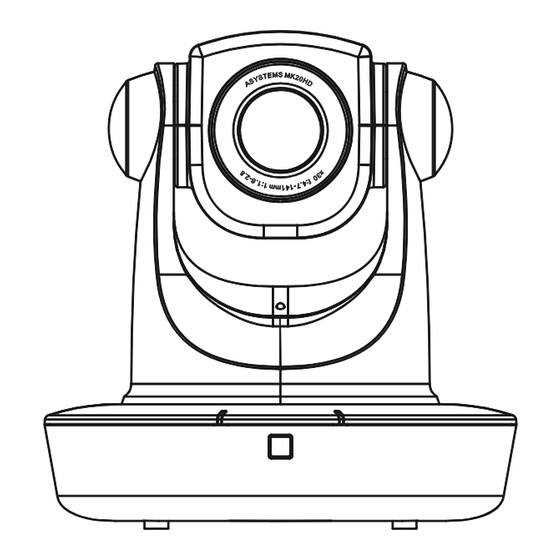
Page 7: Mk20Hd Parts And Functions
MK20HD MK20HD PARTS AND FUNCTIONS Front View 144mm Tally Lights Power LED Standby LED Front IR Sensor Front View RS485 Addr & IR Select Tally In RS422/485 IN DC Power Jack Rear IR Sensor SDI Out Kensington Lock HDMI 1 Out... - Page 8 MK20HD Top View swivel base Bottom View 75mm VESA Mount 90mm English...
-
Page 9: Check The Included Items
User’s Manual Pan/Tilt/Zoom Camera MK20HD IR Remote with 2 AAA Batteries MK20HD Owner’s Manual Main Unit Mounting Screw (M4) x 4 Bracket Mounting Screws (M3) x 3 Drop Prevention Wire Screws (M3) x 2 Ceiling Mount Brackets (A & B) -
Page 10: Precautions For Installation
Read the “Installation Instructions” thoroughly and then perform the operation correctly and safely. Also, always read the “Read this first!” of this manual as they contain important information. After the installation, give the “MK20HD Owner’s Manual” to the customer for future use. Ensure that the installation work complies ●... - Page 11 This is normal and not indicative of disconnect the power plug from the power any trouble. outlet. Asystems does not assume any responsibility for accident or damage during installation if procedure in this manual is not followed. English...
-
Page 12: Ceiling Mount Installation
MK20HD CEILING MOUNT INSTALLATION The procedure given here is for the kind of installation where the unit is suspended from an overhead surface, but the same steps are followed for a stand-alone installation. If the ceiling panel is not strong enough to bear the unit’s weight, use the kind of mount bracket that is supported by anchor bolts between the concrete ceiling and ceiling panel. - Page 13 MK20HD 2. Mount the bracket (A) to the MK20HD camera. ● Use the bracket mounting M4 screws supplied with the unit to attach the bracket (A) to the VESA mount on the base of camera. Main unit mounting screws (M4) x 2 (supplied)
- Page 14 MK20HD 4. Mount the unit. ● The hooks on bracket (B) can be inserted to the corresponding holes to bracket (A) to form a hinge, once inserted, turn the bracket (B) counterclockwise to lock it in place. 5. Secure the mounting brackets in place.
-
Page 15: Precaution For Use
MK20HD PRECAUTION FOR USE ● Handle carefully Do not drop the product, or subject it to strong shock or vibration ● Use the product in an ambient temperature of 32 °F to 122 °F (0 °C to 50 °C). Avoid using the product at a cold place below 32 °F (0 °C) or at a hot place above 122 °F (50 °C). -
Page 16: How To Connect The Unit
MK20HD HOW TO CONNECT THE UNIT 1. Connect the video output cable via HDMI 1, HDMI 2 or SDI cable. 2. Connect the RJ-45 cable if the camera is to be controlled by a PTZ camera remote control. 3. Connect the AC adaptor and power cable that comes included with the camera. -
Page 17: Dip Switch Setting
DIP SWITCH SETTING The DIP Switch on the back of the MK20HD is solely used for manually setting the unit’s ID. Each of the five adjustable levers is correspondent to the common binary value. The first two levers are for IR remote ID 1 to 3, the last three levers are RS485 connection ID 1 through 5 when the camera is connected and controlled by a PTZ camera controller using the RS485 protocol. -
Page 18: Operating Precautions
MK20HD OPERATING PRECAUTIONS Shoot under the proper lighting conditions When using the automatic functions To produce pictures with eye-pleasing colors, ● If “Full Auto” has been selected as the setting shoot under the proper lighting conditions. for Scene on the camera menu, for example,... - Page 19 MK20HD Turn off the power before connecting or Do not allow foreign matter to make contact disconnecting the cables. with the rotating parts Always be sure to turn off the power before Otherwise, damage may be caused. connecting or disconnecting the cables.
-
Page 20: Ir Remote
MK20HD IR REMOTE The MK20HD comes equipped with a wireless remote, and the unit can be operated by using the wireless remote control. Check out the following points before using the wireless remote control. ● Point the wireless remote control at the unit’s wireless remote control IR sensor areas (shown in the figures), and operate it within a range of 10 meters (32.8 ft) from these areas. -
Page 21: Camera Settings
MK20HD CAMERA SETTINGS User can manually adjust the camera settings with the MENU button of the remote control. Whenever changes are made, user must save in order the register and apply the changes made by selecting item “20. SAVE & EXIT”. -
Page 22: Layout Of Wireless Remote Control Ir Sensor Areas
MK20HD LAYOUT OF WIRELESS REMOTE CONTROL IR SENSOR AREAS Front View Rear View Rear IR Sensor Front IR Sensor Top View English... -
Page 23: Ir Remote Parts And Functions
Toggle on screen status display on and off. 6. PRESET MEMORY CALL BUTTONS 0 ‑ 9 MK20HD can store up to 10 preset memories, these are used to call the information on the unit’s directions and other settings that have been registered in the unit’s preset memories. - Page 24 ENTER button confirms the user selection. 13. PAN‑TILT BUTTONS AND MENU OPERATION BUTTONS ↑↓←→ ● These are used to change the MK20HD’s direction. The unit is tilted in the up/down direction using the ↑ and ↓ buttons and panned in the left/right direction using the ←...
- Page 25 MK20HD 19. ZOOM + & ‑ ZOOM + & - are used to adjust the lens zoom. The zoom is adjusted in the wide-angle using the - button and in the telephoto using the + button. 20. FOCUS + & ‑...
-
Page 26: Specifications
MK20HD SPECIFICATIONS Features Descriptions Type 1/2.8” Type Exmor™ CMOS Pixels HD 2.4MPixels Illumination 0.5 Lux @ F1.6 White Balance Auto/Manual Sensor Gain Control Auto/Manual Back-light On/Off Compensation E-Shutter 1/1 to 1/10,000 sec S/N Ratio >50 dB Focus F=4.7-141mm F1.6-2.8 Lens... - Page 27 NOTES...
- Page 28 www.asystems-sys.com...
Need help?
Do you have a question about the MK20HD and is the answer not in the manual?
Questions and answers