Table of Contents
Advertisement
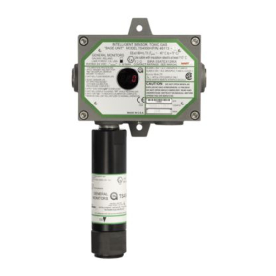
Model TS4000H
Intelligent Sensor for
Toxic Gas Detection
The information and technical data disclosed in
this document may be used and disseminated
only for the purposes and to the extent
specifically authorized in writing by General
Monitors.
Instruction Manual
02-17
General Monitors reserves the right to change
published specifications and designs without
prior notice.
MANTS4000H
Part No.
MANTS4000H
Revision
P/02-17
Advertisement
Table of Contents

Subscribe to Our Youtube Channel
Related Manuals for General Monitors TS4000H


Summary of Contents for General Monitors TS4000H
- Page 1 General Monitors. Instruction Manual 02-17 General Monitors reserves the right to change published specifications and designs without prior notice. MANTS4000H Part No. MANTS4000H...
- Page 2 TS4000H This page intentionally left blank.
-
Page 3: Table Of Contents
TS4000H Table of Contents TABLE OF FIGURES ......................... VII TABLE OF TABLES ........................VIII ABOUT THIS MANUAL ....................... 1 Format Conventions ..........................1 Notes, Cautions, and Warnings ....................1 Menu Formats ..........................1 Modbus Register Formats ......................1 Other Sources of Help ..........................1 Contacting Customer Support .................... - Page 4 TS4000H 3.6.1 Start-up Readiness Checklist ..................26 3.6.2 Start-up Process ......................27 Maintaining Explosion Proof Integrity ..................27 4.0 OPERATION ......................... 29 Start-up Checklist ........................29 User Menu Structure ........................ 29 User Menu Display ........................31 Start-up ............................ 32 Using the Selection Magnet ..................... 33 Selectable Options ........................
- Page 5 5.9.45 MOD2 Hardware Clear Error (0x004E) ............... 68 5.9.46 MOD2 Clear Communication Errors (0x004F) ............68 5.10 TS4000H Run Time Meter and Real Time Clock (Time/Date) ..........68 5.11 Conversion between Run Time Meter and Time/Date Clock ........... 69 5.12 Event Logging ..........................
- Page 6 TS4000H General Monitors’ Offices......................78 9.0 APPENDIX ..........................79 Warranty ........................... 79 Conversion Matrix – Percent of Scale to Scaled Value ............80 Periodic Testing / Calibration of Field Devices ................ 83 Periodic System Verification ....................83 Specifications ........................... 84 9.5.1...
-
Page 7: Table Of Figures
TS4000H Table of Figures Figure 1: Base Unit ..............................8 Figure 2: Interface Module ............................. 9 Figure 3: Electrochemical Cell Assembly ......................10 Figure 4: Mounting Dimensions ........................... 15 Figure 5: Local Configuration Diagram ........................ 16 ... - Page 8 Table 4: Required Tools ............................12 Table 5: Gas Combination Table ......................... 13 Table 6: TS4000H to GM Display Device DC Ground Connections ..............23 Table 7: TS4000H Terminal Block TB1 Pinouts ....................23 Table 8: Connection to GM Display Device 4-20 mA Connections ..............23 Table 9: Connection to Control Room Modbus Devices ..................
-
Page 9: About This Manual
WARNING: cause injury to people working with the equipment. Menu Formats TS4000H User Menu keywords and LED digital display messages are shown in bold (example: rSt). Modbus Register Formats Hexadecimal numbers are used in Modbus registers and are indicated by the addition of either “0x”... -
Page 10: Before Installation
The TS4000H Base Unit is rated Explosion Proof (XP) and the Interface Module WARNING: Intrinsically Safe (IS) for use in hazardous locations. - Page 11 SPECIAL CONDITIONS OF SAFE USE PERTAINING TO ATEX/IECEx INSTALLATIONS: The TS4000H shall not be used as a Safety Related Device as defined by ATEX Directive 94/9/EC, The Intelligent Sensor Toxic Gas Interface Module Type TS4000(H) shall be installed on a suitably certified Flameproof or Increased Safety enclosure.
-
Page 12: Glossary Of Terms
TS4000H The Interface Module Type TS4000(H) must be protected by a fuse with a breaking capacity of 1500A fitted in the external circuits. 1.4 Glossary of Terms Table 1: Glossary of Terms Term / Definition Abbreviation Amperes Alternating Current American Wire Gauge... - Page 13 TS4000H Term / Definition Abbreviation been removed National Pipe Thread Over voltage return OV Return Power Supply Common Ground 0VDC Combining with Oxygen Oxidation Printed Circuit Board Programmable Logic Controller Parts per million A chemical reaction in which one or more electrons are transferred from...
-
Page 14: Product Overview
2.0 Product Overview 2.1 General Description The TS4000H is a +24 VDC-powered toxic gas detector comprised of a Base Unit, Interface Module, and Electrochemical Cell (sensor) – refer to Sections 2.4, 2.5, and 2.6, respectively, for more information. The TS4000H supports a wide range of General Monitors’ approved electrochemical cells, and operates as a universal toxic gas detector by simply replacing and calibrating sensors. -
Page 15: Applications
Water and Waste Table 2: Sample Industry Applications 2.4 Base Unit The TS4000H Base Unit provides the display / control device for the entire TS4000H. The Base Unit is built on the proven Intelligent Sensor platform and incorporates the following key features: ... -
Page 16: Interface Module
The TS4000H Interface Module is encapsulated in an anodized aluminum housing enabling sensor information to be processed at the point of detection. The TS4000H provides a 4-20 mA output signal proportional to 0 to 100% FS gas concentration at the Base Unit. -
Page 17: Figure 2: Interface Module
TS4000H Figure 2: Interface Module... -
Page 18: Electrochemical Cell
The counter electrode acts to balance the reaction at the sensing electrode. Figure 3: Electrochemical Cell Assembly NOTE: The oxygen sensor does not have an identification board. Nonetheless, the TS4000H will automatically configure a fully functional oxygen cell. NOTE: For... -
Page 19: Installation
Powering up the TS4000H Table 3: Installation Overview 3.1 Unpacking the Equipment All equipment shipped by General Monitors is packaged in shock absorbing containers that protect against physical damage. The contents should be carefully removed and checked against the enclosed packing list. -
Page 20: Required Tools
TS4000H: To Find a Suitable Installation Location 1. Locate the TS4000H near potential gas leak sources and away from excessive heat, light, wind, dust, water, vibration, shock, and radio frequency interference (RFI). For Environmental Specifications, refer to Section 9.5. -
Page 21: Installation Overview
Do not paint the TS4000H assemblies. If the Base Unit is painted, the LED CAUTION: display cannot be read. If the Interface Module is painted, the gas is not able to diffuse into the sensor. -
Page 22: Intrinsic Safety Barrier
If the facility has been altered, placement may need to be adjusted 3.4 Mounting Instructions Mount the TS4000H using the bolt holes on the Base Unit. For easy access and readability, the Base Unit may be mounted away from the Interface Module (remote configuration). -
Page 23: Mounting Dimensions
TS4000H 3.4.1 Mounting Dimensions The following figure shows the mounting dimensions for the TS4000H. Figure 4: Mounting Dimensions... -
Page 24: Mounting - Local Configuration
2. Ensure the open slots of the gas passage are straight up and down to enable the gas to rise up and through the electrochemical cell. 3. Using the two bolt holes, mount the TS4000H Base Unit to a stable surface or wall. NOTE: Duct Mounting Kits are available from General Monitors. For more information, contact... -
Page 25: Mounting - Remote Configuration With External Junction Box
In addition to the standard local configuration – Base Unit and Interface Module mounted in the same location – the TS4000H also supports remote placement of the Interface Module using an external junction box. Refer to Section 9.5.1 for compatible junction boxes. -
Page 26: Wiring Connections
Detection Location Guidelines listed in Section 3.2.2. Environmental Specifications listed in Section 9.5. To Mount the TS4000H – Remote Configuration 1. Mount the TS4000H Base Unit vertically to reduce the possibility of dirt and dust building up on the display window. ... -
Page 27: Figure 7: Wiring Diagram - Local Configuration
TS4000H Control Room TS4000H Base Unit TS4000H Note Interface Module 1. Drawing not to scale. 2. Refer to section 9.5 (Table 41) for MAX wire lengths (BU to IM). 3. The electrochemical cell should always point downward when mounted. Figure 7: Wiring Diagram – Local Configuration... -
Page 28: Wiring Safety Notices
TS4000H Control Room TB 1 TB 3 TS4000H Base Unit TB 2 Junction Box Note TS4000H Interface 1 . Drawing not to scale. Module 2 . Refer to section 9 .5 ( Table 41 ) for MAX wire lengths ( BU to IM ). -
Page 29: Base Unit Wiring
TS4000H 3.5.2 Base Unit Wiring Figure 9 shows the TS4000H terminal block connectors TB1, TB2, and TB3 that hold the wiring that connects the TS4000H to local alarms and control room equipment. You must remove the cover from the TS4000H Base Unit to access these connectors. The inside cover includes a label listing the function of each connector location. -
Page 30: Connecting To The Power Supply Dc Ground
1. Connect the Base Unit terminal block TB1-8 to the power supply Common (0 VDC). 2. If the TS4000H is being used with a +24V power supply and an industrial analog to digital (A/D) converter, the negative supply (COM) of all three devices must be connected. -
Page 31: Connecting Control Room Devices To The Tb1 Block
3.5.4 Connecting Control Room Devices to the TB1 Block The TB1 terminal block supports the connection from the TS4000H Base Unit to a power supply. It also has several types of output signal connections that can be forwarded to readout modules, display devices, and other control room equipment. -
Page 32: Connecting To The +24 Vdc Power Supply
Table 10: Connections to Remote Calibration and Relay Reset Devices 3.5.5 Connecting to the +24 VDC Power Supply The TS4000H operates on +24 VDC power. You must connect the TS4000H to a primary DC power source. For Information on the maximum distance between the TS4000H and the control room equipment, refer to Section 9.5. -
Page 33: Connecting Alarm Relay Devices To The Tb3 Block
TS4000H To Connect the TS4000H to the Power Supply +24 VDC 1. Connect the TS4000H TB1-9 connector to the power supply +24 VDC terminal. The power supply manual for the location of this terminal. 2. For power connections to GM device power supplies, review the following table. -
Page 34: Applying Power And Starting Operation
30 V RMS/42.4 V peak or 8 A @ 30 VDC resistive max. 3.6 Applying Power and Starting Operation Once the mounting, cabling, and alarm relay installation is complete, the TS4000H is ready to begin the power-on sequence. Please read this section carefully before applying power to the TS4000H. -
Page 35: Start-Up Process
.0015 inch or .038 mm. There are three unused entry holes in each TS4000H Base Unit housing: one on the left, one on the right, and one on the bottom. These entry holes are used as follows:... - Page 36 When a TS4000H Interface Module is attached to the Base Unit or a remote junction box for remote configuration, it must be screwed into the Base Unit / remote junction box housing using...
-
Page 37: Operation
This section offers detailed instructions for completing several start-up operation and configuration tasks using the TS4000H menu system. Information regarding use of the TS4000H Modbus commands as an alternate method for operating and configuring the unit is provided in Section 5.0, Modbus Interface. -
Page 38: Figure 12: User Menu Structure
TS4000H Figure 12: User Menu Structure... -
Page 39: User Menu Display
TS4000H NOTE: If the TS4000H is ordered without relays or Modbus communications, changing the relay or Modbus settings will have no effect on the operation of the unit. 4.3 User Menu Display The following table explains the User Menu abbreviations displayed on the 3-digit 7-segment... -
Page 40: Start-Up
Calibration Modes, refer to Sections 4.8 and 4.9, respectively. NOTE: During power-up, the Base Unit may briefly display “F1” after displaying the software revision letter. NOTE: A new sensor may take up to sixty minutes to stabilize once installed in the TS4000H. -
Page 41: Using The Selection Magnet
TS4000H 4.5 Using the Selection Magnet To navigate the User Menu, you must use the supplied General Monitors magnet. It allows the user to access the built-in magnetic switch without compromising the explosion proof integrity of the Base Unit. Figure 13: Selection Magnet To Use the Magnet 1. -
Page 42: Selectable Options
TS4000H 4.6 Selectable Options The TS4000H contains a number of user configurable options that can be selected using the supplied magnet. Figure 15: Selectable Options 4.6.1 Sensor Range The Sensor Range is configured automatically by the TS4000H when a new electrochemical cell is plugged into the Interface Module. -
Page 43: Warning Relay Settings
TS4000H 3. Apply and remove the magnet to see the sensor range appears on the display. Apply the magnet to cycle through the ranges, and remove the magnet to select the correct range on the display. When “Fi” of the sensor range menu displays, apply and remove the magnet to exit this menu. -
Page 44: Alarm Relay Settings
TS4000H To Adjust the Warning Relay Settings for All Sensors except O 1. Apply and hold the magnet on the GM logo on the Base Unit cover. Wait until “SE” displays and then remove the magnet. This action places the unit into Setup Mode. - Page 45 TS4000H Latching (default) De-energized (default) 60% FS set point (default) 95% of FS (maximum) Warn relay set point (minimum) The default Alarm Relay settings for O are: 17.0% by volume (default) Warn relay set point (maximum) ...
-
Page 46: Modbus Channel 1 Settings
TS4000H To Adjust the Alarm Relay Settings for O 1. Apply and hold the magnet on the GM logo on the Base Unit cover. Wait until “SE” displays and then remove the magnet. This action places the unit into Setup Mode. -
Page 47: Modbus Channel 2 Settings
TS4000H 19,200 baud “192” 9,600 baud “96” 4,800 baud “48” 2,400 baud “24” 4. To select the Channel 1 data format, apply and remove the magnet when “For” displays. The current format is then displayed. If another data format is required, apply and hold the magnet until the required data format displays, and remove to select the required data format. -
Page 48: Hart/Modbus Select
4.6.6 HART/Modbus SELECT This option is not shown if HART was not purchased for the TS4000H. When HART is selected via setup, the Modbus Channel 2 setup is not displayed or available. When Channel 2 is changed from HART to Modbus, the previous Modbus Channel 2 settings are used. -
Page 49: Relay Reset
3. The relays can be reset using the Remote Reset input terminals on TB1. Connect a normally open switch between terminal TB1-7 and TB1-8. Closing the switch momentarily resets the relays. General Monitors’ explosion proof switch, P/N 30051-1 can be used for this purpose and installed in one of the unused ¾” conduit entries on the TS4000H. -
Page 50: Gas Check Mode
NOTE: The test gas concentration must be at least 10% FS before the unit can complete the Gas Check sequence. If the TS4000H is placed in the Gas Check Mode and no gas is applied within ten minutes, the unit returns to normal operation. If the TS4000H is in Gas Check Mode and gas is applied longer than ten minutes, the unit will also revert to a Fault condition. -
Page 51: Calibration Mode
NOTE: It is not possible to abort or end the Gas Check Mode once gas is applied. 4.8.1.3 Transferring from Gas Check Mode to Calibration The TS4000H can be transitioned directly from Gas Check Mode to Calibration Mode by reapplying and removing the magnet to the GM logo, after applying gas and allowing for the sensor reading to stabilize. - Page 52 FS and will eventually drop to “0.” If a unit time out occurs the user receives a calibration fault. The TS4000H is now calibrated and the sensor calibration constants are stored in the non- volatile memory (EEPROM).
-
Page 53: Remaining Sensor Life
4.11 Calibration Equipment – Portable Purge Calibrator A Portable Purge Calibrator is used for field calibration of the TS4000H. The operational / storage temperature range for the Portable Purge Calibrator is 0°F to +130°F (-18°C to +54°C). -
Page 54: Table 16: Sensor Flow Rates
The unit is now calibrated and the new calibration constants are stored in the EEPROM. For calibration accessories from General Monitors, refer to Sections 9.5.4 and 9.7. Use Table 16 to determine 50% of full scale for the different gases that are monitored. -
Page 55: Modbus Interface
The TS4000H provides the ability of communicating via the industry standard Modbus protocol, while acting as the slave device in a typical master / slave configuration. Upon receiving an appropriate query from the master, the TS4000H will respond with a formatted message as defined below. -
Page 56: Modbus Read Status Protocol (Query / Response)
A maximum of 69 registers can be requested during a single block of time. Table 18: Modbus Read Register(s) Request Upon receiving a valid read register request from the master device, the TS4000H will respond with a message as described in Table 19. If the query generates an error, an exception message is returned to the master device (refer to Section 5.7). -
Page 57: Modbus Write Command Protocol (Query / Response)
TS4000H 5.6 Modbus Write Command Protocol (Query / Response) A master device writes to a TS4000H register by sending a properly formatted 8-byte message as described in Table 20. Byte Modbus Range Referenced to TS4000H Slave Address 1-247* (Decimal) TS4000H ID (Address) -
Page 58: Exception Responses And Exception Codes
An abnormal communication between the two devices produces one of four possible events: 1. If the TS4000H does not receive the query due to a communications error, then no response is returned from the TS4000H and the master device will eventually process a timeout condition for the query. -
Page 59: Exception Code
Exception Code Field: In a normal response, the TS4000H returns data and status in the response data field. In an exception response, the TS4000H returns an exception code (describing the TS4000H condition) in the data field. Below is a list of exception codes that are supported by the TS4000H:... -
Page 60: Command Register Locations
Status / Indicates errors 16-Bit 0x0002 40003 Error Sensor Raw Raw sensor voltage output 16-Bit 0x0003 40004 Data Identifies the TS4000H model number 16-Bit 0x0004 40005 Model in decimal (4007) Software Indicates the software revision 2 ASCII 0x0005 40006 Revision Temperature Sensor temperature output (C + 100) - Page 61 TS4000H Register Master I/O Parameter Function Value Access Address Address Sensor Read the sensor full scale 8-Bit 0x0018 40025 Scale Read and change sensor type (write Sensor 8-Bit R / W 0x0019 40026 CO, CL S, NH , SO only) Type 0x001A –...
- Page 62 TS4000H Register Master I/O Parameter Function Value Access Address Address Read to return number of IM-to-BU IM Com communication errors. Write 0 to clear 16-Bit 0x002E 40047 Errors errors 0x002F – 40048 - 40067 Not Used 0x0042 Total Total number of receive errors on...
- Page 63 TS4000H Register Master I/O Parameter Function Value Access Address Address Running time meter (number of Runtime 16-Bit 0x0051 40082 seconds) Hi word Meter Running time meter (number of Runtime 16-Bit 0x0052 40083 seconds) Lo word Meter 16-Bit: Upper Byte:0-99 Real Time...
- Page 64 TS4000H Register Master I/O Parameter Function Value Access Address Address Alarm Number of seconds stored in Hi word 16-Bit 0x0060 40097 Seconds for an alarm event log entry Time Hi Alarm Number of seconds stored in Lo word 16-Bit 0x0061...
- Page 65 TS4000H Register Master I/O Parameter Function Value Access Address Address Fault 0x006E 40111 Reserved Fault Event Fault event counts 16-Bit 0x006F 40112 Count Maintenance Number of seconds stored in Hi word 16-Bit 0x0070 40113 Seconds for a maintenance event log entry...
- Page 66 TS4000H Register Master I/O Parameter Function Value Access Address Address 16-Bit: Upper Calibration Byte:0 – 59 Real Time Hi byte – min, low byte – sec for a minute, 0x007C 40117 Clock calibration event log entry Lower Byte:0 Minute, – 59 second...
-
Page 67: Command Register Details
16-bit value. The scaling is 0-65535 decimal, which corresponds to 0-21.7 mA. 5.9.2 Mode (0x0001) A read returns the present mode of the TS4000H. A write command changes the mode to the requested mode. EXCEPTION: Returns an Exception Code 03 (Illegal Data Value) if an illegal write is requested. -
Page 68: Status / Error (0X0002)
Major errors that prohibit the TS4000H from operating in a safe manner and result in the unit going offline. The TS4000H will not inform the user of Bad Error any gas being present. -
Page 69: Sensor Raw Data (0X0003)
The Modbus identification number for the TS4000H is 4007. 5.9.6 Software Revision (0x0005) A read returns the software revision of the TS4000H utilizing two ASCII characters. 5.9.7 Sensor Temperature Output (0x0006) A read returns the sensor temperature output in C + 100, a 16-bit value. -
Page 70: Alarm Relay Settings (0X000D)
1 (enable HART) or 0 (disable HART). 5.9.10 Alarm Relay Settings (0x000D) A read returns the present Alarm settings of the TS4000H. A write command changes the settings to the requested values. The set points are programmable in 1% FS steps. -
Page 71: Mod1 Address (0X000F)
TS4000H Byte Function Bit Position Access Not Used Read High 15 MSB Not Used Read Not Used Read Not Used Read Not Used Read Not Used Read Latching / Non-Latching Read / Write Energized / Read / Write De-Energized Set point... -
Page 72: Mod2 Address (0X0012)
TS4000H EXCEPTION: If the data format is not in range, an Illegal Data Value (03) is returned. 5.9.15 MOD2 Address (0x0012) A read command returns the current address for MOD2. A write command changes the address to the requested values. Valid addresses are 1-247 decimal. Factory default is 2. -
Page 73: Sensor Scale (0X0018)
TS4000H 5.9.20 Sensor Scale (0x0018) A read returns the current sensor scale. Sensor scale value is determined automatically by sensor type, and cannot be written over Modbus. For a list of available sensor scales and associated sensor types, refer to Table 34... -
Page 74: Mod1 Total Receive Errors (0X0020)
TS4000H 5.9.22 MOD1 Total Receive Errors (0x0020) A read indicates the total Modbus Communication Receive Errors that occurred in the slave device. The maximum count is 65535. Beyond 65535 the count resets to zero and begins counting again. 5.9.23 MOD1 Total Data Errors (0x0021) A read indicates the total number of illegal data write attempts that occurred in the slave device. -
Page 75: Mod1 Hardware Total Receive Errors (0X002A)
TS4000H 5.9.31 MOD1 Hardware Total Receive Errors (0x002A) A read indicates the total Hardware UART errors that occurred in the slave device. The maximum count is 65535 and then the counter will rollover to zero and begin counting again. The total errors are an accumulation of the individual communication errors of registers 0x0027 –... -
Page 76: Mod2 Crc High Byte Errors (0X0048)
CRC High Byte Errors, and CRC Low Byte Errors to 0. Only a write of value “0” is allowed for this register. 5.10 TS4000H Run Time Meter and Real Time Clock (Time/Date) There is a run time meter and real time clock (Time/Date) in the TS4000H detector. -
Page 77: Conversion Between Run Time Meter And Time/Date Clock
TS4000H The run time meter indicates that the TS4000H is operating in the time of seconds. The meter starts at zero second when it is first powered up, updates every second and saves in the non- volatile memory every 24 hours of the device operating. The meter stops running if the device power is off, and when the device power is on, it will reload the seconds in the non-volatile memory. -
Page 78: Fault Event
TS4000H 5/20/2005 10:15am). Throughout this document the first scenario is called run-time and the second is called real-time. These two scenarios cannot be used interchangeably; if the user wants real time stamps, they must always set the clock after power-up; otherwise they must never set the clock. -
Page 79: Warning Event
TS4000H 5.12.1.4 Fault Real Time Year and Month (0x006A) A read will return the year and the month of a fault event. The year range is [0 – 99], the month is [1 - 12]. 5.12.1.5 Fault Real Time Day and Hour (0x006B) A read will return the day and the hour of a fault event. -
Page 80: Alarm Event
TS4000H 5.12.2.5 Warning Real Time Minute and Second (0x005C) A read will return the minute and the second of a Warning event. The minute range is [0 – 59], the second is [0 – 59]. 5.12.2.6 Warning Event Count (0x005F) A read will return the number of the logged warning events. -
Page 81: Maintenance Event
TS4000H 5.12.4 Maintenance Event The time that a Gas Check occurs is saved in the maintenance event log. Each successful Gas Check increments the maintenance count. There are a total of 10 event time stamps stored. 5.12.4.1 Maintenance Seconds Time Hi (0x0070) A read will return the upper seconds stored in Hi word for a Maintenance event log entry. - Page 82 TS4000H 5.12.5.2 Calibration Seconds Time Lo (0x0079) A read will return the upper seconds stored in Lo word for a Calibration event log entry. The maximum value is 65535 or 0xFFFF in hex. 5.12.5.3 Calibration Real Time Year and Month (0x007A) A read will return the year and the month of a Calibration event.
-
Page 83: Maintenance
TS4000H. 6.2 Storage The TS4000H should be stored in a clean, dry area and within the temperature and humidity ranges specified in Section 9.5. For long-term storage, remove the electrochemical cell and re-install the shorting wire. Place the electrochemical cell in the original container and close the lid. -
Page 84: Troubleshooting
0 mA, the Fault relay de-energizes, and a Fault Code is displayed. Table 35 lists the ten fault conditions monitored by the TS4000H, along with suggestions for resolving these faults. If repeated attempts to resolve the faults are unsuccessful, return the TS4000H to the factory or authorized service center for repair. -
Page 85: Table 36: Fault Code Priorities
NOTE: The recommended power cable resistance for the TS4000H is 20 Ω per conductor (40 Ω loop), at +24 VDC. NOTE: These faults are not overridden by an alarm or warning condition, and always have higher priority over all other faults. -
Page 86: Customer Support
TS4000H 8.0 Customer Support 8.1 General Monitors’ Offices Area Phone / Email UNITED STATES 26776 Simpatica Circle Phone: +1-949-581-4464. 800-446-4872 Lake Forest, CA 92630 Email: info.gm@MSAsafety.com IRELAND Ballybrit Business Park Galway Phone: +353-91-751175 Republic of Ireland, H91 H6P2 Email: info.gmil@MSAsafety.com... -
Page 87: Appendix
9.0 Appendix 9.1 Warranty General Monitors warrants the TS4000H to be free from defects in workmanship or material under normal use and service within two (2) years (one (1) year for electrochemical cells) from the date of shipment. General Monitors will repair or replace without charge any equipment found to be defective during the warranty period. -
Page 88: Conversion Matrix - Percent Of Scale To Scaled Value
TS4000H 9.2 Conversion Matrix – Percent of Scale to Scaled Value Full Scale Value % of Scale 1.00 3.00 10.0 20.0 25.0 0.00 0.00 0.01 0.03 0.02 0.06 0.03 0.09 0.04 0.12 0.05 0.15 0.06 0.18 0.07 0.21 0.08 0.24 0.09... - Page 89 TS4000H Full Scale Value % of Scale 1.00 3.00 10.0 20.0 25.0 0.42 1.26 10.5 0.43 1.29 10.8 0.44 1.32 11.0 0.45 1.35 11.3 0.46 1.38 11.5 0.47 1.41 11.8 0.48 1.44 12.0 0.49 1.47 12.3 0.50 1.50 10.0 12.5 0.51...
-
Page 90: Table 38: Conversion Matrix - Percent Of Scale To Scaled Value
TS4000H Full Scale Value % of Scale 1.00 3.00 10.0 20.0 25.0 0.87 2.61 17.4 21.8 0.88 2.64 17.6 22.0 0.89 2.67 17.8 22.3 0.90 2.70 18.0 22.5 0.91 2.73 18.2 22.8 0.92 2.76 18.4 23.0 0.93 2.79 18.6 23.3 0.94... -
Page 91: Periodic Testing / Calibration Of Field Devices
TS4000H 9.3 Periodic Testing / Calibration of Field Devices Periodic testing and calibrating of the TS4000H should be performed according to the schedules and procedures outlined in the TS4000H Instruction Manual. Testing and calibration procedures should include, but are not limited to the following: ... -
Page 92: Specifications
TS4000H 9.5 Specifications Specification Description Electrochemical cell Sensor Type 2 to 3 years under normal conditions Typical Life (Electrochemical Cell) - Two years for the Base Unit and Interface Module Warranty - One year for the electrochemical cell - Calibration Errors... -
Page 93: Table 40: Mechanical Specifications - Base Unit
1.0 pounds (0.45 kg) Weight ¾ inch NPT Mounting Anodized Aluminum A356-T6 Housing Table 41: Mechanical Specifications – Interface Module Cable Requirements: 3-wire shield cable. Maximum distance between TS4000H and power source @ 24 VDC nominal: FEET METERS 3430 1040 1900... -
Page 94: Table 43: Electrical Specifications
TS4000H Specification Description Maximum distance between the TS4000H and the power source @ General Purpose Installations 24 VDC nominal is 3,430 feet (1040 meters) 20 to 36 VDC range; +24 VDC nominal 0.120 A Input Power 8A @ 250 VAC/ 8A @ 30 VDC resistive maximum Relay Ratings (3x) SPDT –... -
Page 95: Table 44: Environmental Specifications
+ 1% v/v of oxygen - Oxygen (O ): 0-25% v/v Table 45: TS4000H Toxic Gas Sensor Accuracy Specifications NOTE: Chlorine, chlorine dioxide, and hydrogen chloride electrochemical cells are sensitive to changes in humidity, especially at temperatures above 77°F (25°C). To avoid false alarms caused by humidity variations, it is recommended that alarm set points be set above 20% of the full-scale range. -
Page 96: Junction Boxes
TS4000H 9.5.1 Junction Boxes The following General Monitors junction boxes are compatible with the TS4000H remote configuration: Figure 19: 10252-1 Round Anodized Aluminum Junction Box Figure 20: B13-020-1 European Junction Box... -
Page 97: Splash Guards
TS4000H 9.5.2 Splash Guards The following General Monitors splash guards are compatible with the TS4000H: Figure 21: 45167-1 Splash Guard Used for CI , CIO and NO Gases Figure 22: 70631-2 Splash Guard 9.5.3 Accessories The following General Monitors accessories are compatible with the TS4000H:... -
Page 98: Calibration Accessories
TS4000H 9.5.4 Calibration Accessories The following General Monitors calibration accessories are compatible with the TS4000H: Figure 24: 45172-1 Calibration Plug Assy Figure 25: 1400152-1 Calibration Cup for calibrating with splash guard... -
Page 99: Calibration Schedule
TS4000H Calibration Schedule Establishing a periodic calibration schedule is critical to maintaining optimal product performance. Below is a sample schedule for the TS4000H: Detector Serial Number: ________________________ Location: _____________________ Installation and preliminary calibration. Record date after preliminary calibration is performed: Date: _______________ 24-hour calibration. -
Page 100: Parts And Accessories
The Interface Module, however, is a fully encapsulated device and consequently has no replaceable parts. The part number for various TS4000H parts and accessories is listed below: NOTE: The TS4000H ships with a Base Unit, Interface Module, and specified electrochemical cell. -
Page 101: Table 48: Mounting Accessories
, NO 922-023 Regulator (500 ml/min) For CO, H S, NO, SO 45172-1 Calibration Plug 1400152-1 Calibration Cup (for use with splash guard) Table 49: TS4000H Calibration Accessories Range Cylinder Calibration Kit Part Number Concentration 1400263-1 Ammonia (NH 0 – 50 ppm... -
Page 102: Table 51: Spare Cylinders
TS4000H Range Cylinder Cylinder Type Part Number Concentration 1400262-1 Ammonia (NH 0 – 50 ppm 25 ppm 1400262-2 Ammonia (NH 0 – 100 ppm 50 ppm 1400262-9 Carbon Monoxide (CO) 0 – 100 ppm 50 ppm 1400262-10 Carbon Monoxide (CO) 0 –... -
Page 103: Index
TS4000H Index about this manual features and benefits ..............6 manual, about ............... 1 format conventions accessories for this manual ..............1 calibration ..............90, 93 gas calibration procedure ............42 cylinders ................94 general description flow block ................89 description, general .............. - Page 104 TS4000H dimensions ................. 15 system ................80 instructions ................. 14 starting operation local configuration .............. 16 operation, starting .............. 26 remote configuration ............17 start-up ................26, 32 Note, caution, and warning formats .......... 1 start-up checklist notes and warnings checklist, start-up ...............
- Page 105 Product Disposal Considerations This product may contain hazardous and/or toxic substances. EU Member states shall dispose according to WEEE regulations. For further General Monitors’ product WEEE disposal information please visit: www.MSAsafety.com All other countries or states: please dispose of in accordance with existing federal, state and local...
Need help?
Do you have a question about the TS4000H and is the answer not in the manual?
Questions and answers