Table of Contents
Advertisement
Quick Links
Release
R 1.0
29.11.2005
R 1.1
05.01.2006
R 1.2
17.01.2006
Technical Documentation
TD_Repair_L1-L3_CF110_R1.2.pdf
Service Manual
CF110
Level 1- Level 3 (basic)
Date
Department
BenQMobile CC S CES
BenQMobile CC S CES
BenQMobile CC S CES
Company Confidential
Modification Chapter 5 and 6
2006©BenQ
Release 1.2
Notes to change
New document
Part Modification
11/2005
Page 1 of 49
Advertisement
Table of Contents

Related Manuals for BENQ-SIEMENS CF110


Summary of Contents for BENQ-SIEMENS CF110
- Page 1 Release 1.2 Service Manual CF110 Level 1- Level 3 (basic) Release Date Department Notes to change R 1.0 29.11.2005 BenQMobile CC S CES New document R 1.1 05.01.2006 BenQMobile CC S CES Part Modification R 1.2 17.01.2006 BenQMobile CC S CES...
-
Page 2: Table Of Contents
10 JPICS (Java based Product Information Controlling System) ..........30 11 International Mobile Equipment Identity, IMEI..............36 12 General Testing Information....................37 13 Introduction of Service Repair Documentation Level 3 (basic) – CF110 ......43 14 List of available level 2.5light parts ..................44 15 Hardware requirements ......................44 16 CF110 Board layout.........................45 17 SIM Card Problems .........................46... -
Page 3: Key Feature
Release 1.2 1 Key Feature • Li – Ion Battery Pack Battery • Nominal Capacity: 600 mAh • GSM Capacity: 580 mAh • Power input: 2.0 A (0.6 ms) / 0.25 A (0.4 ms) • Cut – off Threshold 3.2 V •... -
Page 4: Cf110 Interface To Accessories
Release 1.2 2 CF110 Interface to Accessories There are no specific mechanical interfaces to the car cradle. The car cradle is designed to fit the existing design. The I/O-Connector (Lumberg-slim-connector) is in use. The compatible interface is suitable to use the travel charger. -
Page 5: Unit Description Of Cf110
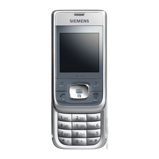
Release 1.2 3 Unit Description of CF110 The CF110 is designed as a slider phone. The slider upper, base upper, base lower and battery cover are painted parts (1k; 2 colours). IMD Lens will be mounted by adhesive, Display, 130X130 TFT; bridgeless keypad, 4-way Navi-Key, 5 keys function keys block, 12 keys number keys block;... -
Page 6: Exploded View Of Cf110
Release 1.2 4 Exploded View of CF110 11/2005 Technical Documentation TD_Repair_L1-L3_CF110_R1.2.pdf Page 6 of 49 Company Confidential 2006©BenQ... -
Page 7: Disassembly Of Cf110
Release 1.2 Disassembly of CF110 All repairs as well as disassembling and assembling have to be carried out in an ESD protected environment and with ESD protected equipment/tools. For all activities the international ESD regulations have to be considered. For more details please check information in c – market https://market.benqmobile.com/SO/welcome.lookup.asp... - Page 8 Release 1.2 Step 3 Remove lower case. Step 4 Disconnect PCB from upper case by using the opening tool. Take care of the flex cable! Step 5 Use tweezers to disconnect the flex cable from the upper case. 11/2005 Technical Documentation TD_Repair_L1-L3_CF110_R1.2.pdf Page 8 of 49 Company Confidential...
- Page 9 Release 1.2 Step 6 Step 7 Remove keypad. Step 8 11/2005 Technical Documentation TD_Repair_L1-L3_CF110_R1.2.pdf Page 9 of 49 Company Confidential 2006©BenQ...
- Page 10 Release 1.2 Step 9 Remove slider. Use opening tool to lift base upper case carefully. Then push it downwards to unhook the slider up. Attention! Take care that the flex cable won’t rip! Step 10 Step 11 Remove screws. Screws size: T3+ Torx. 11/2005 Technical Documentation TD_Repair_L1-L3_CF110_R1.2.pdf...
- Page 11 Release 1.2 Step 12 Remove slider plate by using the opening tool carefully. Push the flex cable trough the cut out. Take care of the flex cable! Step 13 Step 14 Use opening tool to remove the display PCB carefully. 11/2005 Technical Documentation TD_Repair_L1-L3_CF110_R1.2.pdf...
- Page 12 Release 1.2 Step 15 Take out the flex cable with tweezers carefully! It is glued with the earphone! Step 16 To avoid scratches it is mandatory to place a protection foil onto the display! Step 17 Remove keypad MMI by using tweezers carefully.
- Page 13 Release 1.2 Step 18 Step 19 Remove vibramotor by using tweezers carefully. Step 20 Remove microphone by using tweezers carefully. 11/2005 Technical Documentation TD_Repair_L1-L3_CF110_R1.2.pdf Page 13 of 49 Company Confidential 2006©BenQ...
- Page 14 Release 1.2 Step 21 Remove ringer by using opening tool carefully. Step 22 Step 23 Disassemble ringer with tweezers carefully. 11/2005 Technical Documentation TD_Repair_L1-L3_CF110_R1.2.pdf Page 14 of 49 Company Confidential 2006©BenQ...
- Page 15 Release 1.2 Step 24 Step 25 Remove Battery Connector by using Tweezers. Overview Upper Case Parts Overview Lower Case Parts Ringer Display Front cover Metal sheet Slider frame module Ringer frame Battery Vibramotor Connector Pre – Assembled Battery lower sheet Screws Microphone Navy keypad Keypad...
-
Page 16: Assembly Of Cf110
Release 1.2 Assembly of CF110 Step 1 Assemble Battery Connector. Step 2 Use tweezers to fix the ringer in the given frame. Step 3 11/2005 Technical Documentation TD_Repair_L1-L3_CF110_R1.2.pdf Page 16 of 49 Company Confidential 2006©BenQ... - Page 17 Release 1.2 Step 4 Assemble microphone by using tweezers. Consider the correct position of the microphone! Step 5 Use tweeters to assemble vibramotor. Ensure, that the vibramotor contacts are not bent. Step 6 Assemble keypad MMI. 11/2005 Technical Documentation TD_Repair_L1-L3_CF110_R1.2.pdf Page 17 of 49 Company Confidential 2006©BenQ...
- Page 18 Release 1.2 Step 7 Assemble display MMI. Before assembling ensure the correct position of the flex cable with the glued earphone! Step 8 Attention! Before assembling remove display foil and take care of the flex cable! Step 9 Assemble the upper case. 11/2005 Technical Documentation TD_Repair_L1-L3_CF110_R1.2.pdf...
- Page 19 Release 1.2 Step 10 Assemble the upper case. Attention! Be careful with the flex cable! Step 11 Place screws to assemble the upper case. Use a torque screw driver. Step 12 Assemble keypad. 11/2005 Technical Documentation TD_Repair_L1-L3_CF110_R1.2.pdf Page 19 of 49 Company Confidential 2006©BenQ...
- Page 20 Release 1.2 Step 13 Assemble slider. Use opening tool to lift base upper case carefully. Then push it downwards to assemble the slider. Attention! Take care that the flex cable won’t rip! Step 14 To assemble PCB connect it with the flex cable.
- Page 21 Release 1.2 Step 16 Place screws by using the torque screw driver. Step 17 Assemble battery cover. 11/2005 Technical Documentation TD_Repair_L1-L3_CF110_R1.2.pdf Page 21 of 49 Company Confidential 2006©BenQ...
-
Page 22: Benq Service Equipment User Manual
Release 1.2 BenQ Service Equipment User Manual Introduction Every LSO repairing BenQ handset must ensure that the quality standards are observed. BenQ has developed an automatic testing system that will perform all necessary measurements. This testing system is known as: BenQ Mobile Service Equipment •... -
Page 23: Grt Software: Functionality Configuration
Release 1.2 GRT Software: Functionality Configuration Select „Settings >> SWUP / JPICS” Sep 1: Proceed as follows Step 2: Select all required Variants you need to repair (click onto the “+” in front of the product name. Check Com-Port setting. If necessary change it Check speed setting. - Page 24 Release 1.2 Connect to GRM Server Step 3: • Choose in the section „GRM” the „Connect to GRM Database“ functionality Enter your GRT-Username and Password into this fields Activate always both boxes if you connect to the database. Start with “Connect” It you IT infrastructure parameter have changed, use this button to move to the configuration mask...
-
Page 25: Grt Software: Regular Usage
Release 1.2 GRT Software: Regular Usage Select the section SWUpdate Step 1: Choose the area you want to work with Step 2: • Personal Repair Personal Repair is always accessible. Basis for the decision if a SW-Update is authorised by Siemens is the so called Service Release-Table . Example: Mobile Phone has already SW50. - Page 26 Release 1.2 Window explanation This general explanation is valid for all SW-Update channels (Personal Repair, Operator SWAP, Operator SWUpdate) After using „Check Variant“ Phone IMEI- Number will be shown here Window to select the mobile phone CPU Shows the different SW –Versions a) SW inside the mobile phone b) Version of Service Release Table c) Version of Master Table SW...
- Page 27 Release 1.2 Case 1: Personal Repair (green) Step 1: Carry out step 1 – 4 to start SW-Update. Select the mobile phone CPU type Start SW-Update Choose if customer data shall be erased. If “Yes” activate the boxes in front of xfs and mapping 1.1.1.1.1.1.2 Read out phone...
- Page 28 Release 1.2 Case 2: Operator SWAP (red) Step 1: Carry out step 1 – 4 to start SW-Update. Select the mobile phone CPU type Start SW-Update Choose if customer data shall be erased. If “Yes” activate the boxes in front of xfs and mapping 1.1.1.1.1.1.1 Read out phone...
- Page 29 Release 1.2 Case 3 Operator SWUpdate (blue) Step 1: Carry out step 1 – 4 to start SW-Update. Select the mobile phone CPU type Start SW-Update Choose if customer data shall be erased. If “Yes” activate the boxes in front of xfs and mapping 1.1.1.1.1.1.4 Read out phone...
-
Page 30: Jpics (Java Based Product Information Controlling System)
Release 1.2 JPICS (Java based Product Information Controlling System) Overview The following functions are available for the LSO: • General mobile information • Generate PINCODE • Generate SIMLOCK – UNLOCK – Code • Print IMEI labels • Lock, Unlock and Test the BF - Bus 11/2005 Technical Documentation TD_Repair_L1-L3_CF110_R1.2.pdf... - Page 31 Release 1.2 The access to the JPICS server which is located in Kamp – Lintfort is protected by chip card and in addition using secure socket layer (SSL) connection. The JPICS server is only available for authorized users with a specially coded smart card. These smart cards and the administration of the JPICS web server and the PICS database –...
- Page 32 Release 1.2 Installation overview The following installation description assumes that a web browser is already installed. JPICS is tested with the following browsers: 1. Internet Explorer Version 5.5 and higher 2. Netscape Version 6 and higher For further information regarding supported browsers, browser version and supported operating systems, see the Sun FAQ’s.
- Page 33 Release 1.2 Generate Codes In the JPICS application you can choose to generate: • Masterphone codes • Simlock – Unlock – Codes Masterphone codes The Masterphone code is used to unlock blocked mobiles. Masterphone codes can only be supplied for mobiles which have been delivered in a regular manner.
- Page 34 Release 1.2 Simlock – Unlock – Code The Simlock – Unlock – Codes can only be generated if the following conditions are given: • Mobile must have an active Simlock inside. • The user must be given the authorization to obtain Simlock – Unlock – Codes for the variant of the operator to which the mobile was delivered last time.
- Page 35 Release 1.2 Printing IMEI label The module “printing IMEI label” offers the possibility to re-print IMEI labels for mobiles again. You are able to print 1 label in just one step. To prevent that misaligned labels are being printed, the setting “Print test labels = ”...
-
Page 36: International Mobile Equipment Identity, Imei
S30880-S2820-#xxx housing and software variant. CF110 series IMEI label is accessible by removing the battery. Re – use of IMEI label is possible by using a hair – dryer to remove the IMEI label. On this IMEI label, BenQ has also includes the data code for production or service, which conforms to the industrial standard DIN EN 60062. -
Page 37: General Testing Information
Release 1.2 General Testing Information General Information The technical instruction for testing GSM mobile phones is to ensure the best repair quality. Validity This procedure is to apply for all from Siemens AG authorized level 2 up to 2.5e workshops. Procedure All following checks and measurements have to be carried out in an ESD protected environment and with ESD protected equipment/tools. - Page 38 Release 1.2 Incoming check and check after assembling: !! Verify the customers fault description!! After a successful verification pass the defective item to the responsible troubleshooting group. If the fault description can not be verified, perform additional tests to save time and to improve repair quality.
- Page 39 Release 1.2 GSM Test: With the availability of the GRT Test /Alignment software, this tool has to be used to perform the outgoing test! >Connect the mobile/board via internal antenna (antenna coupler) and external antenna (car cradle/universal antenna clip) to a GSM tester >Use a Test SIM For Triple Band phones use a separate test case, if the test software allows only one handover.
- Page 40 Release 1.2 External Antenna Call from MS • GSM900 • Keyboard check • individual • high TCH check • second highest PCL • BS Power = -75 dBm • middle BCCH TX GSM Band 1 • high TCH • Frequency Error •...
- Page 41 Release 1.2 Annex 1 Test SIM Card There are two different “Test SIM Cards” in use: 1) Test SIM Card from the company “ORGA” Pin 1 number: 0000 PUK 1 12345678 Pin 2 number: 0000 PUK 2 23456789 2) Test SIM Card from the company “T-D1” Pin 1 number: 1234 76543210...
- Page 42 Release 1.2 Annex 2 Battery Date Code overview Varta Date code example N 9 A VA Year (N:2001, O:2002...) Supplier Code Month (1:Jan, 2:Feb,…9:Sep, O:Oct, N:Nov, D:Dec) (Maker’s marking) Revision Letter (A, B,…) Hitachi / Maxwell Date code example N 9 A MX Year (N:2001, O:2002...) Supplier Code Month (1:Jan, 2:Feb,…9:Sep, O:Oct, N:Nov, D:Dec)
-
Page 43: Introduction Of Service Repair Documentation Level 3 (Basic) - Cf110
It has to be ensured that every repaired mobile Phone is checked according to the latest released General Test Instruction document (both documents are available in the Technical Support section of the C-market). Check at least weekly C-market for updates and consider all CF110 related Customer Care Information CF110 Partnumber on IMEI label: S30880-S2820-#xxx , while # may be any letter (A-Z) and xxx may be any number from 100, 101, 102.. -
Page 44: List Of Available Level 2.5Light Parts
(according to General soldering information V1.3 - check C-market for updates) Jigs, Tools and working materials for all described repairs: hot air blower soldering gun tweezers flux solder CF110 dome sheet jig 11/2005 Technical Documentation TD_Repair_L1-L3_CF110_R1.2.pdf Page 44 of 49 Company Confidential 2006©BenQ... -
Page 45: Cf110 Board Layout
Release 1.2 CF110 Board layout Upper board side BOARD TO BOARD Connector LED WHITE Lower board side FILTER EMI IO-JACK SLIM CONNECTOR SIM CARD READER 11/2005 Technical Documentation TD_Repair_L1-L3_CF110_R1.2.pdf Page 45 of 49 Company Confidential 2006©BenQ... -
Page 46: Sim Card Problems
Release 1.2 SIM Card Problems Fault Symptoms Customer: GRT: Handset does not accept SIM card SIM Card Problems Back to customer SIM Card Problems without repair Watch for oxidation and caused by customer damaged pads of the SIM Card reader SCRAP - has to be send separately to WSC... -
Page 47: Io Connector Problems
Release 1.2 IO Connector Problems Fault Symptoms Customer: GRT: Charging Problems No connection to GRT Problems with external loudspeaker or microphone when using a car kit Problems with accessories connected at the IO connector Back to customer IO connector Problems without repair Watch for oxidation and caused by customer... -
Page 48: To B Connector (Upper Slider Part) Problems
Release 1.2 B to B connector (upper slider part) Problems Fault Symptoms Customer: GRT: Upper slider keyboard malfunction Keyboard malfunction Upper slider keypad illumination does not work Current measured failed Display problems Back to customer B to B connector problems without repair Watch for oxidation and caused by customer... -
Page 49: Main Keypad Illumination Problems
Release 1.2 Main keypad illumination Problems Fault Symptoms Customer: GRT: Main keypad illumination does not work Current measured failed Back to customer Led’s Problems without repair Watch for oxidation and caused by customer damaged pads of the LED’s okay SCRAP - has to be send separately to WSC - check for twisted or...
Need help?
Do you have a question about the CF110 and is the answer not in the manual?
Questions and answers