
Summary of Contents for Fox FT2
- Page 1 MODEL FT2 THERMAL MASS FLOWMETER & TEMPERATURE TRANSMITTER 399 RESERVATION ROAD MARINA, CA 93933 101364 Revision I...
- Page 2 Please note that Fox Thermal Instruments, Inc. reserves the right to change and/or improve the product design and specification without notice.
-
Page 3: Table Of Contents
4.1.4. Frequency Output ..........................30 4.1.5. Discrete Input/Output ..........................32 4.1.6. RS485 Serial Communication Settings....................33 4.1.7. Display Setup............................35 4.1.8. Password..............................36 4.1.9. Units Settings............................37 4.1.10. Flow Parameters ..........................39 4.1.11. Calibration Parameters.........................42 Fox Thermal Instruments Inc., 399 Reservation Road, Marina, CA 93933 Page i... - Page 4 5.4. Calibration ..............................46 5.5. Fuse Replacement (Standard and NFP version) ..................46 Troubleshooting.....................47 6.1. Replacements Parts............................48 6.2. Return Procedure ............................49 Warranty.........................50 Glossary of Terms and Abbreviations ..............51 Index ........................52 Page ii Fox Thermal Instruments, Inc., 399 Reservation Road, Marina, CA 93933...
-
Page 5: Introduction
1 Atmosphere (14.7 psia), 1 Standard cubic foot of gas equals the mass that is in 1 cubic foot of this gas at 70° F and 1 Atmosphere. The Model FT2 provides a direct measurement of Standard or Mass units with no additional temperature and pressure measurements required. -
Page 6: Block Diagram
1.3. Block Diagram The main parts of the FT2 Mass Flowmeter are: The FT2 main board, the sensor assembly, an optional front panel, and an optional power supply. The two PCBs are mounted inside of the enclosure and the sensor assembly is mounted external to the enclosure. The optional power supply is mounted under the main PCB. -
Page 7: Menu Tree
Stop Bits = 1 HiFloAlm=0 SCFM LoopID = 1 * ONLY available for MODBUS FREQUENCY OUTPUT P/U U/ P FEQ EXIT PLS/UNT = 12.56 MAXFREQ=100 hz MAXFLO= 100 SCFM UNT/PLS=0.876 Fox Thermal Instruments Inc., 399 Reservation Road, Marina, CA 93933 Page 3... - Page 8 Rx= 49.9 Ohm Level2 ShResOfst=0 DISPLAY/PASSWORD Level2 Reset CRC? DSP PSW EXIT Tsv_rt=0.197656 Level2 R20_value=2.5 Level2 DSP1L1= Flo Rate PASSWD=1234 DSP1L2= Flo Total DSP2L1= Temp DSP2L2= Elps time ALTERNATE=Off Page 4 Fox Thermal Instruments, Inc., 399 Reservation Road, Marina, CA 93933...
-
Page 9: Analog 4-20 Ma Outputs
1.8. Communication Features The FT2 offers a RS232 serial link that communicates to a Palm™ PDA handheld or with a PC application for data display and programming. Also, RS485 is available to connect to the optional front panel with an interface to a specific bus converter (Profibus, DeviceNet or Ethernet). The RS485 can connect directly as an optional Modbus interface. - Page 10 Model FT2 101364 Figure 1-3 Dimensions for Flow Body Style with NPT Connections Page 6 Fox Thermal Instruments, Inc., 399 Reservation Road, Marina, CA 93933...
- Page 11 101364 Model FT2 Figure 1-4 Dimensions for Flow Body with Flange Connections Fox Thermal Instruments Inc., 399 Reservation Road, Marina, CA 93933 Page 7...
- Page 12 Model FT2 101364 Figure 1-5 Dimensions for Insertion Style Page 8 Fox Thermal Instruments, Inc., 399 Reservation Road, Marina, CA 93933...
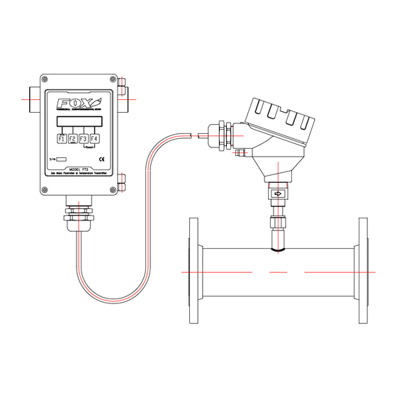
- Page 13 101364 Model FT2 Figure 1-6 Dimensions for Remote NEMA 4 Enclosure Fox Thermal Instruments Inc., 399 Reservation Road, Marina, CA 93933 Page 9...
-
Page 14: Installation
Insertion Style 2.2.1. Mounting – Insertion Style The Model FT2 is mounted through a ¾-inch hole and a ¾-inch female NPT half coupling provided in the customer’s pipe. Installation procedures must be a combination of end user’s best engineering practices, in compliance with local codes, and manufacturer’s recommendations. -
Page 15: Installation Depth
2.2.3. Sensor Orientation Equal length sensor elements: Install flowmeter with both sensor elements facing the flow stream within +/-10 degree. Figure 2-2. Equal Length Sensor Elements. Fox Thermal Instruments Inc., 399 Reservation Road, Marina, CA 93933 Page 11... - Page 16 Note: In extreme low flow measurements (below 30 standard feet per minute), convection heat from the longer probe can affect the shorter probe. In these applications, chose a mounting that prevents this from occurring (ex. Horizontal mounting). Page 12 Fox Thermal Instruments, Inc., 399 Reservation Road, Marina, CA 93933...
-
Page 17: Flowmeter Placement - Insertion Style
2.2.4. Flowmeter Placement - Insertion Style Install the Model FT2 Insertion style flowmeter so that it is far enough away from bends in the pipe, obstructions, or changes in line sizes to ensure a consistent flow profile. Fifteen diameters of straight pipe upstream and ten downstream are recommended. -
Page 18: Flowmeter Placement - Flow Body Style
2.2.5. Flowmeter Placement - Flow Body Style Install the Model FT2 Inline style flowmeter so that it is far enough away from bends in the pipe, obstructions, or changes in line sizes to ensure a consistent flow profile. Eight diameters of straight pipe upstream and four downstream are recommended. -
Page 19: Flow Body Orientation
(see Figure 2-3, View A-A). In these applications, chose a mounting orientation that prevents this from occurring (ex. horizontal mounting). Figure 2-7 Flow Body Orientation Fox Thermal Instruments Inc., 399 Reservation Road, Marina, CA 93933 Page 15... -
Page 20: Start Up
• Do not install the FT2 enclosure near an igniter, igniter controller or switching equipment. • Do not install an external power supply in a cabinet containing an igniter controller or switching equipment. -
Page 21: Power Input Wiring And Grounding
3.2.1. Power Input Wiring and Grounding If the optional AC power supply is supplied by FOX, the input power can be 85 to 250 VAC. If the customer supplies an external power supply, it must supply 24 VDC +/- 10 %, with a minimum of one amp. -
Page 22: To 20 Ma Output Wiring
TS2, 1(+) & 2(-). Connect TEMPERATURE 4 to 20 mA output to TS2, 3(+) & 4(-). Figure 3-3 Isolated Wiring for the 4-20mA Outputs Figure 3-3A Non-Isolated Wiring for the 4-20mA Outputs Page 18 Fox Thermal Instruments, Inc., 399 Reservation Road, Marina, CA 93933... -
Page 23: Frequency/Alarm Output Wiring
The alarm output is selected when JP1 pins 2 & 3 are connected together. Only one of the options can be active at one time. Figure 3-4 Frequency/Alarm Output Wiring Fox Thermal Instruments Inc., 399 Reservation Road, Marina, CA 93933 Page 19... -
Page 24: Rs485 Wiring
W3 and W4 are used for half duplex operation. (W3 connects TX+ & RX+, W4 connects TX- & RX-). Figure 3-5 RS485 Wiring and Configuration Page 20 Fox Thermal Instruments, Inc., 399 Reservation Road, Marina, CA 93933... -
Page 25: Remote Switch Wiring
A remote switch can be used to reset the Totalizer and elapsed time, if enabled by the programming mode. The switch contacts are de-bounced on the FT2 board. There is no polarity requirement on these connections. Use TS2-12 and TS2-13. -
Page 26: Sensor Wiring (4 Wires)
Model FT2 101364 3.2.6. Sensor Wiring (4 wires) Note: Sensor terminations are performed at the factory except when Remote Electronics are provided. Figure 3-7 Sensor Wiring Page 22 Fox Thermal Instruments, Inc., 399 Reservation Road, Marina, CA 93933... -
Page 27: Remote Wiring Installation
(18 AWG recommended). Do not connect the shield at the FT2 enclosure end. On the FT2 board, make sure that the jumper W2 is not across both pins when a 5-wire sensor is supplied (see Figure3-8). -
Page 28: Start Up Sequence
The program automatically enters the Run/Measure mode after power up. If the Local display is installed, the screen will show the software versions for the FT2 and the display module. Refer to section 4.1 Programming using the Local Display. Programming of the flowmeter can also be accomplished using a Palm™... -
Page 29: Local Display Screens
Note: CRC ERROR will flash on the display if a CRC Error is detected while reading the EEPROM. Alarm Code 36 will be displayed in the Alarm Display. Refer to 4.1.14 RESET CRC. Fox Thermal Instruments Inc., 399 Reservation Road, Marina, CA 93933 Page 25... -
Page 30: Engineering Screens
3.7.2. Engineering Screens Pressing F1 and F2 keys at the same time in the normal mode, brings the engineering screens. These screens display internal parameters of the FT2, which are used by Fox service personnel. Flo=1255 SCFM Display # 10 F1 key: Move up one screen Csv=0.45678 Volt... -
Page 31: Resetting Total And Elapsed Time
4 to 20 mA for flow rate is out of range 4 to 20 mA for temperature is out of range ANYBUS communication error RTC Error EEPROM CRC Error Totalizer error detected Fox Thermal Instruments Inc., 399 Reservation Road, Marina, CA 93933 Page 27... -
Page 32: Programming
To Select from a List: FLO UNT = SCFM Press NXT (F1) key repeatedly until the correct selection is made and OK (F4) key to accept the entry. Page 28 Fox Thermal Instruments, Inc., 399 Reservation Road, Marina, CA 93933... -
Page 33: Entering The Programming Mode
The following menu allows the scaling of the analog 4-20 mA outputs. From the base screen, press I/O (F1) and then in the next screen press 420 (F3). SET I/O EXIT Fox Thermal Instruments Inc., 399 Reservation Road, Marina, CA 93933 Page 29... -
Page 34: Frequency Output
Use P/U (F1) to enter pulse per unit, U/P (F2) for Unit per pulse and FEQ (F3) to enter the flow and maximum frequency to scale the frequency output. Page 30 Fox Thermal Instruments, Inc., 399 Reservation Road, Marina, CA 93933... - Page 35 Press FEQ (F3) and the following screen will show: MaxFreq=98.52 Hz Enter the maximum frequency and press OK (F4) (Maximum frequency should not exceed 100 Hz) The next screen will show: Maxflo=2000 SCFM Fox Thermal Instruments Inc., 399 Reservation Road, Marina, CA 93933 Page 31...
-
Page 36: Discrete Input/Output
101364 Note: When the flow rate exceeds the maximum frequency set point, the output will stay at that maximum frequency but the FT2 will issue an alarm code. 4.1.5. Discrete Input/Output To program the discrete input or output, press I/O (F1) key from the base menu... -
Page 37: Rs485 Serial Communication Settings
Press EXIT (F4) repeatedly until “Normal Mode” is seen briefly to exit the programming mode. The JP1 selection jumper needs to be installed between pin 2 & 3 on the main FT2 board to select the isolated digital output for the alarm. - Page 38 Press NXT (F1) to select the baud rate and press OK (F4) Selections are: 19200 9600 4800 2400 1200 Parity=None For Modbus selection only Press NXT (F1) to select the parity and press OK (F4) Selections are: NONE EVEN Page 34 Fox Thermal Instruments, Inc., 399 Reservation Road, Marina, CA 93933...
-
Page 39: Display Setup
From the base programming menu press DSP (F3) to select the display menu: DISPLAY/PASSWORD EXIT 4.1.7.1. To Program the Display: Press DSP (F1) key. The display will show: DSP1L1 = Flo Total Fox Thermal Instruments Inc., 399 Reservation Road, Marina, CA 93933 Page 35... -
Page 40: Password
The Level 1 programmable password can be disabled by setting it to “0”. From the base programming menu press DSP (F3) to select the display menu: DISPLAY/PASSWORD EXIT Page 36 Fox Thermal Instruments, Inc., 399 Reservation Road, Marina, CA 93933... -
Page 41: Units Settings
Lbs/time or Kg/time. These values will be set at FOX, using the Application Data Sheet values. If the customer changes the application, these values can be changed to match the new application. Check with FOX customer service before changing the application gas. - Page 42 MMSCFM WARNING: The FT2 re-calculates area, 4 & 20 ma values, Maximum flow for the frequency output and zero flow cutoff when changing flow units, going to and from volumetric and mass flow. When going to and from Velocity or velocity to velocity, the FT2 will not re-calculate these values and these values must be re-entered manually.
-
Page 43: Flow Parameters
Flow cutoff, pipe area, filter, high and low alarm for flow and temperature. The menu is accessed from the base programming menu by pressing FLO (F2) key: SET PARAMETERS EXIT Fox Thermal Instruments Inc., 399 Reservation Road, Marina, CA 93933 Page 39... - Page 44 The filter value is an exponential filter that dampens the noise and is used as follows: Flow Value = (FA * new value) + (FB * average) where FA = filter value, FA + FB is equal to 1.0. Page 40 Fox Thermal Instruments, Inc., 399 Reservation Road, Marina, CA 93933...
- Page 45 If no checking is needed, this value should be set to zero. Press OK (F4) to accept the value. HiTmpAlm = 230 C Fox Thermal Instruments Inc., 399 Reservation Road, Marina, CA 93933 Page 41...
-
Page 46: Calibration Parameters
Level 2 password. Calibration parameters values are set for temperature and pressure at 0 degree C and 760 mmHg. These settings should normally never be changed except by Fox Thermal Instrument personnel at the factory. This menu is entered from the base menu and pressing FLO, PRM and CAL. -
Page 47: Reset Total And Elapsed Time
If the EEPROM CRC check fails (Error Code 36), the EEPROM values will need to be verified and corrected before clearing the error. Call FOX Customer Service if you need assistance. Fox Thermal Instruments Inc., 399 Reservation Road, Marina, CA 93933... -
Page 48: Simulation
Enter the value and then press OK (F4). Note: Enter zero to disable this feature. TmpSim = 0 C Enter the value and then press OK (F4). Note: Enter zero to disable this feature. Page 44 Fox Thermal Instruments, Inc., 399 Reservation Road, Marina, CA 93933... - Page 49 Press YES (F1) to start the simulation mode, NO (F4) otherwise. Upon pressing either key, the program will return to the FLOW PARAMTER 1 menu. NOTE: Simulation Mode will be cleared if the power is cycled. Fox Thermal Instruments Inc., 399 Reservation Road, Marina, CA 93933 Page 45...
-
Page 50: Preventative Maintenance
A new sensor will be installed and calibrated. Refer to Section 6.2, Return Procedure. 5.4. Calibration To insure continuing high accuracy of your Model FT2 Flow Meter, Fox Thermal Instruments Inc. provides a full NIST traceable calibration. The minimum re-calibration interval is 2 years, unless otherwise recommended by FOX. -
Page 51: Troubleshooting
2. Improper wiring connections for power and/or 4-20mA output signal. The FT2 requires a separate power source for the main board and the two 4-20mA output signals. Two wires supply 24VDC power to the main board. Two wires are used for each of the 4-20 mA output signals. -
Page 52: Replacements Parts
4. Improper sensor wiring The FT2 monitors the sensor signals and will issue an Error Code 22 when a sensor is out of range. If the temperature of the probe is excessive it will shut down the current to the sensor in order to protect it. -
Page 53: Return Procedure
The Fox Thermal Instruments, Inc. Customer Service Department can be reached at (831) 384-4300. Please have the model and serial number available when you call. If it becomes necessary to return a Model FT2 Mass Flow Meter to Fox Thermal Instruments, obtain a Return Material Authorization Number from Customer Service Department. -
Page 54: Warranty
FOX in handling and shipping the returned unit. d. The liability of FOX shall be limited to replacing or repairing, at its option, any defective parts which are returned. Labor and related expenses incurred by the Customer to install replacement parts are not covered by this warranty. -
Page 55: Glossary Of Terms And Abbreviations
Metric Ton per Hour MXFLO Maximum Flow NEMA National Electrical Manufactures Association NIST National Institute of Standards and Technology Normal Liter NLPH Normal Liter per Hour NLPM Normal Liter per Minute Fox Thermal Instruments Inc., 399 Reservation Road, Marina, CA 93933 Page 51... -
Page 56: Index
Theory of Operation, 1 Local Display, 5 To program the display, 35 Measurement Mode, 24 Troubleshooting, 47 Menu Tree, 3 Wiring Installation, 16 Mounting – Flow Body Style, 14 Page 52 Fox Thermal Instruments, Inc., 399 Reservation Road, Marina, CA 93933...
Need help?
Do you have a question about the FT2 and is the answer not in the manual?
Questions and answers