
Subscribe to Our Youtube Channel
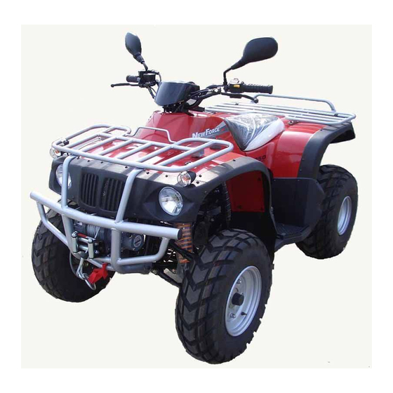
Summary of Contents for New Force Motor NF150
-
Page 1: Table Of Contents
NF150- 150cc Utility Repair Manual CONTENTS 1. INFORMTION 2. MAINTENANCE 3. ENGINE REMOVAL AND INSTALLATION 4. ENGINE FUEL SYSTEM 5. ENGINE LUBRICATION AND COOLING SYSTEM 6. ENGINE COMBUSTION SYSTEM 7. TRANSMISSION SYSTEM 8. FRONT WHEEL AND STEERING SYSTEM 9. REAR WHEEL SYSTEM 10. -
Page 2: Informtion
All information, illustrations, directions and specifications included in this publication are base on the latest product information available at the time of approval for printing. NEW FORCE MOTOR CO., LTD. reserves the right to make changes at any time without notice and without incurring any obligation whatever. - Page 3 1.3 SPECIFICATION ENGINE Type Air-Cooling4-Stroke Displacement 149.5cc Bore and Stroke 57 x 57.8mm Compression 9.2:1 Maximum Torque 1.2kgm@6000rpm Carburetor Kei-hin 009Qga Ignition Capacitor Discharge Starting Electric & Kick Starter Lubrication Oil Pump Supply Transmission Automatic (C.V.T V-belt) and Reverse CHASSIS Overall Length 1720mm Overall Width...
-
Page 4: Serial Number
1.4 SERIAL NUMBER The frame serial number is stamped on the front of the frame. The engine serial number is stamped on the left side of the crankcase. - Page 5 1.5 TORQUE VALUES ENGINE *Cy1inder head hut…………………………………………………………………2.0kgm *Spark plug…………………………………………………………………………1.2kgm *Stud bolt……………………………………………………………………………0.9kgm *Alternator wheel nut…………………………………………………………… …5.5kgm FRAME *Handlebar upper holder bolt………………………………………………………2.7kmg *Steering stem nut…………………………………………………………………..11.0kgm *Steering stem shaft holder bolt…………………………………………………….2.0kgm *Front and rear cushion bolt………………………………………………………...4.0kgm *Steering stem rod nut………………………………………………………………4.0kgm *A arm bolt………………………………………………………………………….4.0kgm *A arm holder bolt…………………………………………………………………..6.0kgm *Front wheel nut…………………………………………………………………..4.5kgm *Disk holder bolt……………………………………………………………………5.5kgm...
-
Page 6: Maintenance
2. MAINTENANCE 2.1 MAINTENANCE DATA 2.8 IDLE SPEED 2.2 MAINTENANCE SCHEDULE 2.9 DRIVE CHAIN 2.3 FUELTUBE 2.10 BRAKE SYSTEM 2.4 THROTTLE OPERATION 2.11 WHEELS AND TIRES 2.5 THROTTLE CABLEADJUSTMENT 2.12 STEERING SYSTEM 2.6 AIR CLEANER 2.13 TOE-IN 2.7 SPARK PLUG 2.14 GEAR OIL 2.1 MAINTENANCE DATA SPECIFICATION... -
Page 7: Throttle Operation
leakage and replace if necessary. 2.4 THROTTLE OPERATION inspect for smooth throttle lever full opening and automatic full closing in all steering positions. Inspect if there is no deterioration or damage in the throttle cable, replace it if necessary. Check the throttle lever, free play is 5-10 mm at the tip of the throttle lever. -
Page 8: Spark Plug
2. 7 SPARK PLUG This spark plug located at the front of the engine . Disconnect the spark plug cap and unscrew the spark plug . Check the spark plug electrodes for wearing . Change a new spark plug if the electrodes and insulator tip appear unusually fouled or burned . -
Page 9: Brake System
Adjust the chain slack. Loose the lock bolts (4pcs) then adjust the drive chain slack by turn the adjusting nut. Tighten the four lock bolts. 2.10 BRAKE SYSTEM Inspect the front brake lever and cable for excessive play or other damage. Replace or repair if necessary. -
Page 10: Wheels And Tires
2.11 WHEELS AND TIRES Inspect the tire surfaces for cuts, nails or other sharp objects. Check the tire surfaces at cold tire condition. The standard of tire pressure is 3.2psi (22kpa). 2.12 STEERING SYSTEM Check the free play of the handle steering front wheels, turn straight ahead. - Page 11 If the toe-in is out of standard, adjust it by changing the length of the steering stem rod equally by turning the steering stem rod. Tighten the lock nuts. torque: 4.Okgrn 2.14 GEAR OIL Gear oil needs to be changed every 30 operating day. There is a gear oil release bolt at the rear of engine.
-
Page 12: Engine Removal And Installation
3. ENGINE REMOVAL AND INSTALLATION 3.1 ENGINE SHALL BE REMOVED IN THE CONDITIONS OF NECESSARY REPAIRMENT OR ADJUSTMENT TO THE TRANSMISSION AND COMBUSTION SYSTEM ONLY 3.2 ENGINE REMOVAL Remove the seat and rear body cover (Chapter 10) Remove the spark plug cap from the spark plug. Remove the exhaust pipe. - Page 13 4.1 TROUBLESHOOTING ENGINE CAN NOT START------------------------------* NO FUEL IN TANK * NO FUEL TO CARBURETOR *TOO MUCH FUEL GO INTO CYLINDE HEAD * NO SPARK AT PLUG * AIR CLEANER CLOGGED ENGINE IDLES UNSTEADY, -------------------------* UNPROPER ADJUSTMENT TO THE IDLE RPM SCREW * IGNITION MALFUNCTION * FUEL/AIR MIXTURE RATIO NO GOOD * AIR CLEANER DIRTY...
- Page 14 4.2 CARBURETOR RE MOVAL RE MOVALTHE AIR CLEANER. DISCONNECT AUTO CHOKE ELECTRIC WIRE. REMOVE THE FUELTUBE AND THE NEGATIVE FUEL TUBE. LOOSEN THE SCREW SO THAT TO LET OUT THE FUEL. LOOSEN THE THROTTLE WIRE ADJ USTING NUT AND THE FIXED NUT. THEN, REMOVE THE THROTTLE WIRE.
-
Page 15: Engine Lubrication And Cooling System
5. ENGINE LUBRICATION AND COOLING SYSTEM 5.1 ENGINE LUBRICATION SYSTEM The pump gears of oil pump is driven by the engine crankshaft. Pump gears rotate the drive shaft in oil pump. This shaft sent the lubricating oil into the crankcase and the crank shaft cam shaft. The oil drops and foam cover the cylinder inner wall, piston surface and piston rings. -
Page 16: Engine Combustion System
6. ENGINE COMBUSTION SYSTEM 6.1 TROUBLESHOOTING LOW COMPRESSION-------* CYLINDER HEAD HEAD GASKET LEAKING OR DAMAGED WARPED OR CRACKED CYLINDER HEAD * CYLINDER OR PISTON RINGS WORN OUT HIGH COMPRESSION------ * EXCESSSIVE CARBON BUILD-UPON PISTON HEAD OR IN COMBUSTION CHAMBER EXCESSIVE NOISE------- * PISTON AND CYLINDER WORN OUT * EXCESSIVE CARBON BUILD-UP EXCESS SMOKE--------... - Page 17 6.2 CYLN HEAD / VALVE REMOVE CAM SHAFT UNSCREW THE FOUR BOLTS WHICH FIX THE HEAD COVER. REMOVE HEAD COVER. UNSCREW CAM CHAIN TENSIONER SCREW, AND TAKE OFF O-RING. TIGHTEN THE CAM CHAIN TENSIONER SCREW IN A CLOCKWISE DIRECTION. UNSCREW THE TWO BOLTS WHICH FIX THE CYLN HEAD.
- Page 18 INSPECT THE CAM SHAFT BRG, IF IT IS WEAROR DAMAGE REPLACE IT REMOVE CAM SHAFT HOLDER USEA 5mm BOLT TO TAKE OUT THE ROCKER ARM SHAFT, STOPER PLATE AND ROCKER ARM. MEASURE THE ACTION OUTER DIAMETERS OF ROCKER ARM SHAFT AND HOLDER. SERVICE LIMIT: 10.10mm ABOVE (HOLDER) MEASURE THE ACTION OUTER DIAMETERS OF ROCKER ARM SHAFT AND ROCKER ARM.
- Page 19 REMOVE CYLN HEAD TAKE OFFTHE DOWEL PIN AND GASKET. REMOVE CAM CHAIN GUIDE. ATTENTION: -- DO NOT HARM THE CYLN INSTALLATION SURFACE. -- PRE VENT ANYTHING FROM DROPPING INTO THE CRANK CASE. DISASSEMBLY CYLN HEAD REMOVE RETAINER, VALVE SPG, SPG SEAT, VALVE STEM SEAL.
- Page 20 6.3 INTALL THE CYLN HEAD DOWEL PIN AND GASKET INSTALL ON THE CYLINDER. INSTALL THE CAM CHAIN TENSIONER. INSTALL THE CYLN HEAD. INSTALL THE CAM HOLDER ASSEMBLY THE CAM HOLDER. MATCH THE “EX ” MARK ON CAM HOLDER WITH THE EX VALVE. TURN THE “T ”...
- Page 21 TIGHTEN THE CYLN HEAD NUT. TORQUE: 2.Okgm LOOSEN THE ADJUST SCREN OF CAM CHAIN IN A ANTI-CLOCKWISE DIRECTION. ADJUSTMENT VALVE CLEARANCE. VALVE CLEARANCE: 0.07 ±0.02mm APPLY LUBRICANT ON THE SURFACE OF NEW O-RING. TIGHTEN NHEAD COVER BOLT.
- Page 22 6.4 REMOVE THE CYLINDER/PISTON REMOVE CYLN HEAD, TAKE OFF CAM CHAIN GUIDE, CYLINDER. REMOVE CYLN GASKET, DOWEL PIN, CLEAR THE LEFT-OVER ON CYLN SURFACE. REMOVE PISTON REMOVE PISTON PIN CLIP. ATTENTION: DO NOT DROPTHE CLIP INTO THE CRANK CASE. MEASURE PISTON AND PISTON RING CLEARANCE.
- Page 23 MEASURE PISTON PIN INNER DIAMETER. SERVICE LIMIT: 15.04mm max MEASURE PIN OUTER DIAAMETER. SERVICE LIMIT: 14.96mm min MEASURE THE PISTON OUTER DIAMETER SERVICE LIMIT: 56.9mm min. PISTON AND PIN CLEARANCE. SERVICE LIMIT: 0.02mm max MEASURETHECYLN INNER DIAMETER. SERVICE LIMIT: 57.1mm max. PISTON AND CYLN CLEARANCE.
- Page 24 INSTALL THE PISTON RING SET. APPLY SOME LUBRICANT ON THE PISTON RING. ATTENTION: -- DO NOT SCRATCH THE PISTON. -- DO NOT BREAK THE PISTON RING. -- THE INDICATOR POINT OF PISION FACE ABOVE. --THE RING SET SHOULD BE TURNING FREELY AFTER INSTALLATION.
-
Page 25: Transmission System
7 TRANSMISSION SYSTEM 7.1 REMOVE DRIVE FACE ASSY REMOVE LCOVER DUCFTUBEAND LCOVER. REMOVE DRIVE FACE, TAKE OFF DRIVE BELT. REMOVE THE DRIVE FACE ASSEMBLY. INSPECF DRIVE BELT WIDTH. SERVICE LIMIT: 17.5mm min DISASSEMBLY THE RAMP PLATE, TAKE OFF SIX ROLLERS... - Page 26 INSPECT THE ROLLER FOR DAMAGE OR WEAR. MEASURE ROLLER OUTER DIAMETER. SERVICE LIMIT: 17.4mm min MEASURE THE MOVABLE DRIVE FACE INNER DIAMETER. SERVICE LIMIT: 24.06 max INSPECT THE DRIVE FACE BOSS FOR DAMAGE OR WEAR. MEASURE BOSS OUTER DIAMETER. SERVICE LIMIT: 23.94 mm min. INSTALL ASSEMBLY MOVABLE DRIVE FACE AND ROLLER, RAMP PLATE.
- Page 27 7.2 REMOVE DRIVEN FACE ASSY UNSCREW DRIVEN FACE NUT. REMOVE CLUTCH OUTER. INSPECT THE CLUTCH OUTER DAMAGE OR WEAR. MEASURE CLUTCH OUTER INNER DIAMETER. MAXIMUM LIMIT: 125.5mm INSPECT THE LINING FOR DAMAGE OR WEAR. MEASURE THE DRIVEN FACE LINING THICKNESS THE MINIMUM LIMIT: 1.5mm IFTHEY ARETHINNERTHAN THE MINIMUM LIMIT, REPLACE THE DRIVEN FACE LININGS.
- Page 28 INSPECI THE DRIVEN FACE FOR WEAR OR DAMAGE. MEASURE THE DRIVEN FACE BOSS OUTER DIAMETER. SERVICE LIMIT: 33.94mm min INSTALL THE MOVABLE DRIVEN FACE INTO THE DRIVEN FACE. PUT IN 9.0 ~ 9 .5g GREASE INTO THE HOLE OF DRIVEN FACE AFTER INSTALLATION. THE SURFACE OF DRIVEN FACE SHOULD BE FREE FROM ANY GREASE.
- Page 29 Dismantle and Assemble Procedures for the Gear 1) Release the air cleaners off from the engine by the screw and nuts fastened on the left side case of engine. Take off the right side floor panel and the drive chain to get working space better. 2) (U.S.
- Page 30 3) Take off the Front Pipe and Muffler Body by its screws and Nuts and release the all flange bolts on the mounting position of engine, such as engine hanger, rear top end and on the bottom side of engine. 4) Lean the vehicle over to the left side to get the engine slide out from its hanger and it is ready for the further work to the engine on the working table.
- Page 31 6) (U.S. model) Take off the C-Clip (7 mm by diameter) and Pivot Pin for the Gear Shift Bar, take off Flange Bolt (M 6 x 12) and Plain washer( I.D. 6.4 mm x O.D. 19 mm x T 1 mm) by the torque of 1.2 Kg-M in wrench for the Gear Shift Spindle Pivot;...
- Page 32 7.3 REMOVE THE KICK START SPINDLE REMOVE LCOVER, DRIVE FACEASSY AND DRIVEN FACE ASSY. REMOVE RETURN SPRING, KICK STARF SPINDLE AND STARTER IDLE GEAR. INSTALL THE KICK START SPINDLE APPLY SOME GREASE AT THE PART OF KICK SPINDLE, THAT PART IS TO BE INSTALLED AT L CASE.
-
Page 33: Front Wheel And Steering System
8. FRONT WHEEL AND STEERING SYSTEM 8.1 TROUBLESHOOTING HARD STEERING----------* FAULTY TIRE * STEERING SHAFF HOLDER TOO TIGHT * INSUFFICIENT TIRE PRESSURE * FAA ULTY STEERING SHAFT BEARINGS * DAMAGED STEERING SHAFT BEARING FRONT WHEEL WOBBLING----- * FAULTY TIRE * WORN FRONT BRAKE DRUM BEARING * BENT RIM * AXLE NUT NOT TIGHTENED PROPERLY BRAKE DRAG-----------... -
Page 34: Handle Bar
8.2 HANDLE BAR REMOVAL Remove the throttle lever housing on the right handle bar. Remove brake lever bracket. Remove engine switch housing on the left handle bar. Remove rear brake level bracket. Remove the bolts attaching the speedometer. Remove the handle bar holder and handle bar. INSTALLATION Put the handlebar on the lower holders. -
Page 35: Front Wheel
Install the switch housing. aligning the boss with the hole. Tighten the upper screw first then tighten the lower one. Install the rear brake lever bracket, aligning the boss with the hole. Tighten the screw securely. Aligning the split line of the throttle housing and holder with the punch mark. -
Page 36: Front Brakes
8.4 FRONT BRAKES FRONT BRAKE INSPECTION Remove the front wheel. Remove the brake drum. Measure the brake lining thickness. The minimum limit: 1 .5mm If they are thinner than the minimum limit, replace the brake linings. Measure the brake drum inner diameter. The maximum limit: 111 mm Turn the inner race of each bearing with fingers. - Page 37 BRAKE PANEL REMOVAL Disconnect the brake cable from the brake arm. Remove the brake panel from the knuckle. Remove brake arm and cam. Remove indicator plate INSTALL BRAKE PANEL Apply grease to the brake cam and anchor pin and install the cam in the brake panel. Install the brake arm on the cam by aligning the punch mark and the groove on the cam.
- Page 38 STEERING STEM ROD INSPECTION Inspect the steering stem rod for damage or bending. Inspect the ball joint rubbers for damage, wear or deterioration. Turn the ball joints with fingers. The ball joints should turn smoothly and quietly. KNUCKLE INSPECTION Inspect the knuckle for damage or cracks. STEERING SHAFT REMOVAL Remove the handle bar and speedometer.
- Page 39 STEERING SHAFT INSPECTION Inspect the steering shaft for damage or cracks. Measure the steering shaft outer diameter in the location of the holder. Minimum limit: ¢31.8mm STEERING SHAFT BEARING INSPECTION Turn the shaft bearing with finger. The bearing is on the front part of frame. The bearing should turn smoothly and quietly.
- Page 40 INSTALLATION OF STEERING STEM ROD Install left steering stem rod with “L “ mark on the wheel side. Install right steering stem rod with “R “ mark on the steering shaft side.
-
Page 41: Rear Wheel System
9. REAR WHEEL SYSTEM 9.1 TROUBLESHOOTING BAD BRAKE PERFORMANCE---------* BRAKE HOSE HAVE AIR * BAD MASTER CYLN BEAKE OIL * DISK DIRTY OR BENT * BRAKE HOSE CLOGGED * BRAKE OIL NO ENOUGH 9.2 REMOVE REAR WHEEL AND REAR BRAKE Let the rear wheels off the ground. - Page 42 Disassembly the chain retaining clip and master link . Disassembly the driven sprocket. Check the driven sprocket for damage or wear. Let the rear axle lie in V-blocks and check the run out . The run out limit is 0.5mm Check the turning of rr axle holder bearing with fingers.
- Page 43 INSTALLATION Add grease to the rr tire axle holder dust seal. Assembly the rear axle and the driven sprocket. Assembly the drive chain on the driven sprocket. Assembly the master link and retaining clip. Note the retaining clip direction. Install the drive chain protector. Torque: 4.0kgm 9.4 REAR BRAKE AND WHEEL INSTALLATION...
-
Page 44: Body Cover And Exhaust Pipe
10. BODY COVER AND EXHAUST PIPE 10.1 REAR BODY COVER REMOVE Find the hook handle bar under the rear body cover. Pull it backward to release the seat. Procedure of remove the rear body cover : Unscrew the four bolts which connect the front body cover and rear body cover. -
Page 45: Exhaust Pipe Installation
10.3 EXHAUST PIPE REMOVE Do not service the exhaust pipe while they are hot. You must wait at least 15 minutes after turn off the engine. Unscrew the two exhaust pipe bolts that fixed with engine. Unscrew the two bolts which connect the FR PIPE and RR PIPE. -
Page 46: Electrical System
11. ELECTRICAL SYSTEM 11.1 TROUBLESHOOTING ENGINE STARTS BUT STOPS--------* IMPROPER IGNITION TIMING * FAULTY SPARK PLUG NO SPARKAT PLUG------------* ENGINE STOP SWITCH AT “OFF “ * FAULTY IGNITION COIL * FAULTY GENERATOR * FAULTY CDI UNIT * POOLY CONNECT ED: Between CDI and ignition coil Between alternator and CDI unit Between CDI and engine stop switch... -
Page 47: Ignition Coil
11.2 IGNITION COIL Remove the spark plug cap from the spark plug. Disconnect the ignition coil primary wire. Measure the primary coil resistance. STANDARD: 0.1-1.0Ω(20ºC) Measure the secondary coil resistance with the spark plug cap in place. STANDARD: 7.0-l2kΩ(20ºC) 11.3 IGNITION TIMING The ignition advance is 13º... -
Page 48: Battery Inspection
11.6 BATTERY INSPECTION Battery is under the seat, you can see this battery from the left side. Measure the battery voltage using a voltmeter. VOLTAGE: Fully charged: 13.1 V Undercharged: Below 12.3V BATTERY REMOVAL Remove the seat, then you can see the battery. Disconnect the negative cable and then the positive cable and remove the battery. - Page 49 11.8 WIRING DIAGRAMS...
-
Page 50: Troubleshooting
12. TROUBLESHOOTING 12.1 ENGINE DOES NOT START POSSSIBLE REASON CHECK FUEL FLOW TO CARBUREFORF N.G. * NO FUEL IN FUEL TANK * CLOGGED FLOAT VALVE * CLOGGED FUEL TANK CAP BREATHER HOLE O.K. * CLOGGED AT FUELTUBE SPARK TEST N.G. * FAULTY SPARK PLUG WEEK OR NO SPARK * FOULED SPARK PLUG... - Page 51 12.2 POOR PERFORMANCE AT LOW AND IDLE SPEED POSSIBLE REASON CHECK INGITION TIMING N.G. * FAULTY C.D.I. UNIT OR PULSE GENERATOR O.K. CHECK CARBURETOR N.G. AIR SCREW ADJUSTMENT * IMPROPERLY ADJUSTEDAIR SCREW O.K. CHECK FOR LEAKING N.G. * DETERIORATED INSULATOR O-RING INTAKE PIPE * LOOSE CARBIJRETOR PERFORM SPARK TEST...
- Page 52 12.3 POOR PERFORMANCE AT HIGH SPEED POSSIBLE REASON CHECK IGNITION TIMING N.G. * FAULTY C.D.I. UNIT * FAULTY PULSE GENERATOR O.K. CHECK FUELTUBE AT * LACK OF FUEL IN TANK FUEL FLOW RESTRICTED CARBURETOR * CLOGGED RJEL LINE * CLOGGED FUEL VALVE * LOGGED FILJELTAANK BREATHER HOLE REMOVE CARBURETOR...
- Page 53 12.4 LOSS POWER POSSIBLE REASON RAISE WHEELS OFF GROUND * BRAKE DRAGGING DOES NOT SPIN FREELY AND SPIN BY HAND * DRIVE CHAIN TOOTIGHT * DAMAGED WHEEL BEARING * WHEEL BEARING NEEDS LUBRICATION SPIN FREELY PRESSURE LOW CHECK TIRE PRESSURE *PUNCTURED TIRE * FAULTY TIRE VALVE PRESSURE NORMAL...
- Page 54 12.5 POOR HANDLING POSSIBLE REASON STEERING IS HEAVY * DAMAGED STEERING BEARING * DAMAGED STEERING SHAFT BUSHING ONE WHEEL IS WOBBLING * BENT RIM IMPROPERLY INSTALLED WHEEL HIJB * EXCESSIVE WHEEL BEARING PLAY * BENT SWINGARM * BENT FRAME * SWINGARM PIVOT BUSHING EXCESSIVELY WORN VEHICLE PULLS TO ONE SIDE * BENT STEERING STEM ROD...
Need help?
Do you have a question about the NF150 and is the answer not in the manual?
Questions and answers
Hi, I have a question about the Nf 150 automatic. The quad is going backwards on neutral backwards in reverse and in forward imat done point it jumps back to reverse or neutral in the middle of driving forward. What can I do in this situation, I unmounted the transmission but I don't see the issue. Please help, this is luckily the only manual I could find