Table of Contents
Advertisement
Please dispose of packaging for the product in a responsible
manner. It is suitable
for recycling.
Help to protect the
environment, take the packaging to the local amenity tip
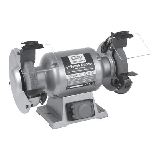
Professional Bench Grinder
and place into the appropriate recycling bin.
Never dispose of electrical equipment or batteries in with
your domestic waste. If your supplier offers a disposal facili-
ty please use it or alternatively use a recognised re-cycling
agent. This will allow the recycling of raw materials and help
protect the environment.
FOR HELP OR ADVICE ON THIS PRODUCT PLEASE CONTACT YOUR DISTRIBU-
TOR, OR SIP DIRECTLY ON:
TEL: 01509500400
07625, 07628 & 07645
EMAIL: sales@sip-group.com or technical@sip-group.com
www.sip-group.com
Please read and fully understand the instructions in this manual
before operation. Keep this manual safe for future reference.
Ref: 230415
28
1
Advertisement
Table of Contents

Related Manuals for SIP 07625

Summary of Contents for SIP 07625
- Page 1 This will allow the recycling of raw materials and help protect the environment. FOR HELP OR ADVICE ON THIS PRODUCT PLEASE CONTACT YOUR DISTRIBU- TOR, OR SIP DIRECTLY ON: TEL: 01509500400 07625, 07628 & 07645 EMAIL: sales@sip-group.com or technical@sip-group.com www.sip-group.com...
-
Page 2: Declaration Of Conformity
Machinery Directive 2006/95/EC Low Voltage Directive 2004/108/EC EMC Directive 2002/95/EC RoHS Directive And the relevant harmonised standard(s), including, EN 55014-1:2006+A2:2011 EN 55014-2:1997+A2:2008 EN 61000-3-2:2006+A2:2009 EN 61000-3-3:2013 Signed: …………………………………... Mr P. Ippaso - Managing Director - SIP (Industrial Products) Ltd Date: 24/10/2014. - Page 3 Operating Instructions Flanged nut 5mm WK05-00105 Rubber foot WK05-00134 Maintenance Left spark arrestor WK05-00167 Screw M5x16 WK05-00137 Exploded Drawing - 07625 Screw M5x20 WK05-00104 Right spark arrestor WK05-00182 Parts List - 07625 End cap WK05-00168 Right wheel guard WK05-00183 Exploded Drawing - 07628...
-
Page 4: Safety Symbols Used Throughout This Manual
Read all these instructions before operating the grinder and save this user manual for future reference. SIP recommends that this grinder should not be modified or used for any application other than that for which it was designed. It was designed to be bench mounted, for driving abrasive wheels for the purpose of sharpening cutting tools such as chisels or drill bits. - Page 5 PARTS LIST 07628 SAFETY INSTRUCTIONS...cont locked cupboard wherever possible and out of the reach of children. Ref. No. Description Sip Part No. Ref. No. Description Sip Part No. WEAR THE CORRECT CLOTHING: Do not wear loose clothing, neckties, rings, bracelets,...
- Page 6 SAFETY INSTRUCTIONS...cont EXPLODED DRAWING 07628 have. REMOVE ADJUSTING KEYS AND WRENCHES: Form a habit of checking to see that keys and adjusting wrenches are removed from the tool before every use. DO NOT OVERREACH: Keep proper footing and balance at all times. USE THE RIGHT TOOL: Do not use the tool or attachment to do a job for which it was not designed.
- Page 7 PARTS LIST 07625 SAFETY INSTRUCTIONS...cont Ref. No. Description Sip Part No. Ref. No. Description Sip Part No. Only use grinding wheels that are rated for the correct speed. Do not overload the grinding wheel; stalling the machine will shorten its life.
-
Page 8: Technical Specifications
TECHNICAL SPECIFICATIONS EXPLODED DRAWING 07625 Part No. 07625 07628 07645 Description 6” Bench Grinder 8” Bench Grinder 10” Bench Grinder Input Voltage 230v 50Hz 230v 50Hz 230v 50Hz Motor 370w 550w 750w Wheel Speed 2850rpm 2850rpm 2850rpm Duty Cycle S2, 30 minutes... -
Page 9: Electrical Connection
MAINTENANCE….cont ELECTRICAL CONNECTION Hold the grinding wheel, or the opposite one, with one hand and turn the retain- These grinders are fitted with a standard UK type 230v ~ plug. Before using the grinder inspect the cable and plug to ensure that neither are damaged. If any damage is ing nut clockwise for the left hand wheel, and anti clockwise for the right hand visible have the grinder inspected / repaired by a suitably qualified person. -
Page 10: Contents And Accessories
GUARANTEE MAINTENANCE….cont These SIP Bench Grinders are covered by a 12 month parts and labour warranty cover- Inner Flange Outer Flange ing failure due to manufacturers defects. This does not cover failure due to misuse or Shaft Wheel operating the grinders outside the scope of this manual - any claims deemed to be outside the scope of the warranty may be subject to charges Including, but not lim- ited to parts, labour and carriage costs. - Page 11 MAINTENANCE….cont CONTENTS AND ACCESSORIES….cont REPLACING THE GRINDING WHEELS 07625 & 28 07645 1. Bench Grinder c/w 2 x Grinding Wheels (not pictured). Warning! Always ensure that a ’blotter’ (cardboard disc between the flange 2. Spark Arrestor x 2. and the grinding wheel) is fitted either side of the grinding wheel.
-
Page 12: Getting To Know Your Bench Grinder
GETTING TO KNOW YOUR BENCH GRINDER OPERATING INSTRUCTIONS….cont Warning! Always ensure that the grinder is bolted down onto a secure sur- face prior to operation. SWITCHING THE GRINDER ON/OFF The grinder is fitted with an NVR (No Volt Release) switch; This means that if power is cut to the grinder it will not restart once the power is restored to the grinder. - Page 13 ASSEMBLY INSTRUCTIONS FITTING THE TOOL REST 07645 FITTING THE SPARK ARRESTOR 07625 & 28 The tool rest fits to the inside of the guard towards the bottom (Fig. 9). There are 2 holes on the inside of the guards (Fig. 1); A smaller one towards the front to Use the supplied 2 x bolts and washers to secure in place (Fig.
- Page 14 Fig. 7 Fig. 8 Fig. 5 Follow these instructions to fit the 2nd tool-rest to the opposite side (07625 & 07628 only). Note: Take care not to over tighten the bolt as this will damage the guard; It only needs to be tight enough to hold the eye shield in place whilst allow-...
Need help?
Do you have a question about the 07625 and is the answer not in the manual?
Questions and answers