Table of Contents
Advertisement
Advertisement
Table of Contents

Summary of Contents for Shinkawa VM-7 Series
- Page 1 MANUAL No. 20901E1.6 Published in Feb. 2009 Revised in Jun. 2010 VM-7 Series Monitor System Manual Read this manual thoroughly and understand the contents before use. Keep this manual so that the operator can refer to it when needed. SHINKAWA Sensor Technology, Inc.
-
Page 3: Regarding The Manual For The Vm-7 Series Monitor
Thank you very much for purchasing the VM-7 Series Monitor. <Regarding the Manuals for the VM-7 Series Monitor> The VM-7 Series Monitor (hereafter “the unit”) comes with four manuals which contain information for different operations as well as tasks. This "MCL View Operation Manual" is one of the four. -
Page 4: Important Notices
Company and product names contained herein are trademarks or registered trademarks of their respective owners. Copyright is retained by Shinkawa Sensor Technology, Inc. No part of this document may be disclosed or reproduced in any form without prior consent of SHINKAWA Sensor Technology,... -
Page 5: Disclaimer
VM-7 System Manual Preface <Disclaimer> The company assumes no liability for any damage or injury caused by the user's fault including not following the instructions of this manual or not installing or handling the unit in an appropriate manner. The company shall not be liable for any direct or indirect damage, injury, or lost income resulting from misuse, abuse, modification to or of any part of, or disassembling of the unit by the user. -
Page 6: Table Of Contents
VM-7 System Manual Chapter 2 Description of the System <Table of Contents> Page Regarding the Manual for the VM-7 Series Monitor ...............1 Important Notices..........................2 Disclaimer ............................3 Table of Contents ..........................4 Chapter 1 For Safe Use of the Unit.................5 Warning Symbols ....................5 Precautions for handling..................5... -
Page 7: Chapter 1 For Safe Use Of The Unit
VM-7 System Manual Chapter 2 Description of the System Chapter 1 For Safe Use of the Unit For safe use of the unit, be sure to read this manual before use. Warning Symbols This manual uses the following symbols to increase awareness of possible dangers or harmful situations to the user, and to guide in the safe operation of the unit. -
Page 8: Chapter 2 Description Of The System
VM-7 System Manual Chapter 2 Description of the System <Compliances> WARNING When installing this unit, read "VM-7 Series Monitor Installation Manual" and follow the instructions. Failure to do so may result in malfunction of the unit, fire or injury. CAUTION Before installation, be sure to read the manuals for this unit as well as other instruments that are to be connected. -
Page 9: System Outline
Chapter 2 Description of the System Chapter 2 Description of the System System outline VM-7 Series Monitor is a system which provides full-time on-line monitoring of various rotating machineries. Signals transmitted from the sensor installed to rotating machineries are input to the monitor module. -
Page 10: Unit Part Name And Functions
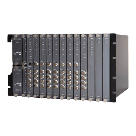
VM-7 System Manual Chapter 2 Description of the System Unit part name and functions VM-7 system monitor is provided with the slots, Slot 0 to 10, in which each module is installed. Slot P1 Slot P2 Slot 10 Slot 0 Name Functions ①... - Page 11 VM-7 System Manual Chapter 2 Description of the System <Instrument Rack (VM-76)> An instrument rack comes in two different models: a Eurotype input/output terminal type (VM-761) and a batch input/output panel connector type (VM-762). An instrument rack is an assembly to accommodate each module and fix it onto the panel. All the modules are mounted in the slots inside an instrument rack.
- Page 12 VM-7 System Manual Chapter 2 Description of the System Name Function Performs the following according to contact inputs. Contact input terminal Self-hold alarm reset ⑥ block Activation of sequence function Activation of 10 pole high pass filter System-OK output Provides contact outputs according to OR of OK ⑦...
- Page 13 VM-7 System Manual Chapter 2 Description of the System D-sub I/O connector type Instrument Rack (VM-762) Name Function Monitor output Provides monitor outputs (buffer output or reshaped ① connector rotary pulse output). Monitor output Provides buffer output and pulse output of the phase ②...
- Page 14 VM-7 System Manual Chapter 2 Description of the System Name Function Analysis Module ⑨ communication Outputs data processed by the Analysis Module. connector The measurement value and status of each monitor is Network communication ⑩ transmitted to the network via the Network connector 1 Communication Module installed on the Slot 1.
- Page 15 VM-7 System Manual Chapter 2 Description of the System <Vibration/Displacement Monitor Module (VM-701)> The Vibration/Displacement Monitor Module is a monitor that monitors the vibration level and position of the shaft of rotating machineries, and thermal expansion difference between the rotor and casing.
- Page 16 VM-7 System Manual Chapter 2 Description of the System <Absolute Vibration Monitor Module (VM-702)> The Vibration Monitor Module is a dedicated monitor that monitors the relative/absolute vibration level of the rotary machine shafts, or relative vibration and seismic vibration simultaneously. This module is compatible with up to 2 input systems (relative vibration: 2 channels, seismic vibration: 2 channels).
- Page 17 VM-7 System Manual Chapter 2 Description of the System Name Function Outputs 2ch input signal. There are the following three methods to output signals, and the signal to be output is set through FIELD CONFIG. Outputs input signals through the buffer amplifier 2ch monitor output ⑥...
- Page 18 VM-7 System Manual Chapter 2 Description of the System <Tachometer & Eccentricity Monitor Module (VM-703)> Tachometer & Eccentricity Monitor Module is a monitor that has a function to monitor rotation speed/acceleration of the shaft and to monitor shaft eccentricity while the rotation machine is started.
- Page 19 VM-7 System Manual Chapter 2 Description of the System ⑪ Main board A board on which electronic parts are mounted ⑫ DIN connector A connector used for connecting to the motherboard...
- Page 20 VM-7 System Manual Chapter 2 Description of the System <Temperature Monitor Module (VM-704)> The Temperature Monitor Module is a monitor that monitors the temperatures of rotating machineries. A single module provides up to six channels for input, and can monitor the temperature of six different locations on the machine.
- Page 21 VM-7 System Manual Chapter 2 Description of the System ⑨ DIN connector A connector used for connecting to the motherboard...
- Page 22 VM-7 System Manual Chapter 2 Description of the System <Rod Drop Monitor Module (VM-706)> The Rod Drop Monitor Module is a monitor the measure for “the abrasion of the rider of a reciprocating compressor”. This module is compatible with up to four channel inputs and a phase marker input. Also, this module provide the recorder output corresponding to input signals and contact output, to outside equipment via the rear panel of the instrument rack.
- Page 23 VM-7 System Manual Chapter 2 Description of the System Name Function 5ch Monitor Output ⑨ Outputs 5ch input signal via the buffer amplifier. Connector 5ch pulse output Shapes 5ch input signal into rectangular wave to ⑩ connector output. This is used to fix the Vibration/Displacement ⑪...
- Page 24 VM-7 System Manual Chapter 2 Description of the System <18-Channel Relay Module (VM-721)> The 18-Channel Relay Module relates the DANGER, ALERT and OK alarm to a specific logic, and outputs that result as a contact signal via the rear panel of the instrument rack. The 18-Channel Relay Module can be installed on Slot 10 of the instrument rack only.
- Page 25 VM-7 System Manual Chapter 2 Description of the System <Local Communication & Phase Marker Module (VM-741)> The Local Communication & Phase Marker Module serves as an interface for each monitor module, display PC and service PC. It also detects and indicates the DANGER, ALERT, OK alarm of each module installed in the instrument rack.
- Page 26 VM-7 System Manual Chapter 2 Description of the System Name Function Normal: Does not light. When the DANGER BYPASS has been set and warning is not output: Lights (in red). DANGER BYPASS ④ When the DANGER BYPASS has been set and indicator warning is output: Flashes.
- Page 27 VM-7 System Manual Chapter 2 Description of the System <Network Communication Module (VM-742)> The Network Communication Module transmits the static data of each module using Modbus/TCP. Up to 2 modules can be installed in the instrument rack so that the upper network communication becomes redundant.
- Page 28 VM-7 System Manual Chapter 2 Description of the System <Analysis Module (VM-731)> The Analysis Module transmits the analysis data of each module using Ethernet (100Base-T), e.g. waveform, overall, vector of vibration. The Analysis Module can be installed in Slot 8 and 9 or Slot 9 and 10 only in the instrument rack. Name Function When the module is normal: Lights (in green).
- Page 29 VM-7 System Manual Chapter 2 Description of the System <Analysis Module (VM-732)> The Analysis Module transmits the analysis data of each module using Ethernet (100Base-T), e.g. waveform, overall, vector of vibration. This module provides up to two channels for phase marker signals. The Analysis Module can be installed in Slot 8 and 9 or Slot 9 and 10 only in the instrument rack.
- Page 30 VM-7 System Manual Chapter 2 Description of the System 3ch monitor output ⑦ Outputs 3ch input signal via the buffer amplifier. connector 3ch pulse output Shapes 3ch input signal into rectangular wave to ⑧ connector output. 4ch monitor output ⑨ Outputs 4ch input signal via the buffer amplifier.
- Page 31 VM-7 System Manual Chapter 2 Description of the System <Power Supply Module (VM-75)> The Power Supply Module supplies DC powers to each module via a power bus. Also, this informs of an output malfunction with the power status indicator and "Power-OK". Mounting two Power Supply Modules enables a redundant power.
- Page 32 VM-7 System Manual Chapter 2 Description of the System Software name and functions VM-7 Series Monitor uses two types of software: MCL View and FIELD CONFIG. <MCL View (VM-771)> MCL View displays measurement values and the status of each module.
- Page 33 VM-7 System Manual Chapter 2 Description of the System Analysis Module use Analysis View software. < Analysis View (VM-773)> The Analysis View software displays the set value, measurements, and the status of the Analysis Module. And displays the Analytical data.
-
Page 34: Regular Inspection
VM-7 System Manual Chapter 3 Maintenance/Inspection Chapter 3 Maintenance/Inspection Regular inspection To ensure the performance and stability of the unit, it is recommended to check the unit once a year. For the calibration procedure, refer to the Service Manual. Service life of the unit It is recommended to replace the unit after ten years of use at an ambient temperature (approx. -
Page 35: Chapter 4 Troubleshooting
VM-7 System Manual Chapter 4 Troubleshooting Chapter 4 Troubleshooting Problems Possible causes Measures There is no power The power is not supplied to the Confirm the power. input. unit. (The Power status Not connected to the power Connect the wire properly. Indicator doesn't terminal properly light.) - Page 36 VM-7 System Manual Chapter 4 Troubleshooting...
- Page 37 VM-76 INSTRUMENT RACK VM-7 SERIES SPECIFICATIONS Page 1 of 2 No entry if additional Model Code / Additional Spec. Code ( spec, codeis not specified. VM-76 /NB1/TRP I/O type Non-incendive * Tropical spec. European I/O Terminal Type Class I Division 2 CSA...
- Page 38 VM-76 INSTRUMENT RACK VM-7 SERIES SPECIFICATIONS Page 2 of 2 VM-762 Terminal Block / Connector Specification TRANSDUCER INPUT CONNECTOR MONITOR OUTPUT CONNECTOR for PHASE MARKER Type and number : 37pin D-sub (female) × 10pieces Type and number : 9pin D-sub (female) × 1piece...
- Page 39 VM-701 VIBRATION / DISPLACEMENT VM-7 SERIES MONITOR MODULE SPECIFICATIONS Page 1 of 4 No entry if additional Model Code / Additional Spec. Code ( spec, code is not specified. VM-701 /NB1 /CSU /TRP /TB Non-incendive * Custom set up Tropical spec.
- Page 40 VM-701 VIBRATION / DISPLACEMENT VM-7 SERIES MONITOR MODULE SPECIFICATIONS Page 2 of 4 Specification □ ACCESSORY SPECIFICATION CODE / IDENTIFIED BY TB ENVIRONMENTAL CONDITION Code Accessory Quantity (Part Code) Operating temperature : 0 to +65°C /TB1 Transducer input terminal plug (15-pin) Storage temperature : -30 to +85°C...
- Page 41 VM-701 VIBRATION / DISPLACEMENT VM-7 SERIES MONITOR MODULE SPECIFICATIONS Page 3 of 4 Plug/ Terminal Block (Connector) Pin Assignment VM-761Instrument Rack 1 Monitor Output Connector (Back) 2 Transducer Input Terminal Block 3 Recorder Output Terminal Block 4 Contact Output Terminal Block...
- Page 42 VM-701 VIBRATION / DISPLACEMENT VM-7 SERIES MONITOR MODULE SPECIFICATIONS Page 4 of 4 Plug/ Terminal Block (Connector) Pin Assignment VM-762 Instrument Rack 1 Monitor Output Connector (Back) 2 Transducer Input Connector 3 Recorder Output Connector 4 Contact Output Terminal Block...
- Page 43 VM-702 ABSOLUTE VIBRATION VM-7 SERIES MONITOR MODULE SPECIFICATIONS Page 1 of 4 No entry if additional Model Code / Additional Spec. Code ( spec, code is not specified. VM-702 /NB1 /CSU /TRP /TB Non-incendive * Custom set up Tropical spec.
- Page 44 VM-702 ABSOLUTE VIBRATION VM-7 SERIES MONITOR MODULE SPECIFICATIONS Page 2 of 4 Specification □ ACCESSORY SPECIFICATION CODE / IDENTIFIED BY TB Code Accessory Quantity (Part Code) /TB1 Transducer input terminal plug (15-pin) Note2) FRONT-MC-1.5/15-STF-3.81 (Phoenix Contact) : 2pieces (7072NAB) Recorderr output terminal plug (6-pin) Note2) FRONT-MC-1.5/6-STF-3.81 (Phoenix Contact)
- Page 45 VM-702 ABSOLUTE VIBRATION VM-7 SERIES MONITOR MODULE SPECIFICATIONS Page 3 of 4 Plug/ Terminal Block (Connector) Pin Assignment VM-761Instrument Rack 1 Monitor Output Connector (Back) 2 Transducer Input Terminal Block 3 Recorder Output Terminal Block 4 Contact Output Terminal Block...
- Page 46 VM-702 ABSOLUTE VIBRATION VM-7 SERIES MONITOR MODULE SPECIFICATIONS Page 4 of 4 Plug/ Terminal Block (Connector) Pin Assignment VM-762 Instrument Rack 1 Monitor Output Connector (Back) 2 Transducer Input Connector 3 Recorder Output Connector 4 Contact Output Terminal Block Back of Instrument Rack...
- Page 47 VM-703 TACHOMETER & ECCENTRICITY VM-7 SERIES MONITOR MODULE SPECIFICATIONS Page 1 of 5 No entry if additional Model Code / Additional Spec. Code ( spec, code is not specified. VM-703 /NB1 /CSU /TRP /TB Non-incendive * Custom set up Tropical spec.
- Page 48 VM-703 TACHOMETER & ECCENTRICITY VM-7 SERIES MONITOR MODULE SPECIFICATIONS Page 2 of 5 Number of Teeth and Angle θs Setting Angle θs Number of accuracy teeth (deg) (deg) 90.0 ――― ――― ――― ――― ――― ――― ――― ±30.0 225.0 ――― ―――...
- Page 49 VM-703 TACHOMETER & ECCENTRICITY VM-7 SERIES MONITOR MODULE SPECIFICATIONS Page 3 of 5 Default Value INPUT (Tachometer) OK ALARM (Tachometer) Monitoring : Tachometer OK set point : -1.4V (Low) Monitor range : 0 to 5000rpm Reset : AUTO-RESET Input sensor...
- Page 50 VM-703 TACHOMETER & ECCENTRICITY VM-7 SERIES MONITOR MODULE SPECIFICATIONS Page 4 of 5 Plug/ Terminal Block (Connector) Pin Assignment 1 Monitor Output Connector VM-761 Instrument Rack (Back) 2 Transducer Input Terminal Block 3 Recorder Output Terminal Block 4 Contact Output Terminal Block...
- Page 51 VM-703 TACHOMETER & ECCENTRICITY VM-7 SERIES MONITOR MODULE SPECIFICATIONS Page 5 of 5 Plug/ Terminal Block (Connector) Pin Assignment VM-762 Instrument Rack 1 Monitor Output Connector (Back) 2 Transducer Input Connector 3 Recorder Output Connector 4 Contact Output Terminal Block...
- Page 52 VM-704 TEMPERATURE VM-7 SERIES MONITOR MODULE SPECIFICATION Page 1 of 4 No entry if additional Model Code / Additional Spec. Code ( spec, code is not specified. VM-704 /NB1 /CSU /TRP /TB Non-incendive * Custom set up Tropical spec. I/O terminal block for:...
- Page 53 VM-704 TEMPERATURE VM-7 SERIES MONITOR MODULE SPECIFICATION Page 2 of 4 Default Value INPUT CONTACT Input points Contact (RELAY1) : OR (DANGER-1 / DANGER-2 / DANGER-3) Input transducer 100Ω 3-wire RTD (R100/R0=1.3851) Contact (RELAY2) : OR (ALERT-1 / ALERT-2 / ALERT-3) Monitor range 0 to 200°C...
- Page 54 VM-704 TEMPERATURE VM-7 SERIES MONITOR MODULE SPECIFICATION Page 3 of 4 Plug/ Terminal Block (Connector) Pin Assignment VM-761 Instrument Rack (Back) 1 Transducer Input Terminal Block 2 Recorder Output Terminal Block 3 Contact Output Terminal Block Back of Instrument Rack...
- Page 55 VM-704 TEMPERATURE VM-7 SERIES MONITOR MODULE SPECIFICATION Page 4 of 4 Plug/ Terminal Block (Connector) Pin Assignment VM-762 Instrument Rack (Back) 1 Transducer Input Connector 2 Recorder Output Connector 3 Contact Output Terminal Block Back of Instrument Rack Plug/ Terminal Block (Connector) Pin Assignment...
- Page 56 VM-706 ROD DROP MONITOR MODULE VM-7 SERIES SPECIFICATIONS Page 1 of 4 No entry if additional Model Code / Additional Spec. Code ( spec, code is not specified. VM-706 /NB1 /CSU /TRP /TB Non-incendive * Custom set up Tropical spec.
- Page 57 VM-706 ROD DROP MONITOR MODULE VM-7 SERIES SPECIFICATIONS Page 2 of 4 Default value INPUT (ROD DROP) OK ALARM Rod drop : -1.4V (Low), -18.8V (High) Monitor range : 0 to 2mm Phase marker : -1.4V (Low) Input transducer : FK-202F (non-intrinsic safety)
- Page 58 VM-706 ROD DROP MONITOR MODULE VM-7 SERIES SPECIFICATIONS Page 3 of 4 Plug/ Terminal Block (Connector) Pin Assignment VM-761 Instrument Rack 1 Monitor Output Connector (Back) 2 Transducer Input Terminal Block 3 Recorder Output Terminal Block 4 Contact Output Terminal Block...
- Page 59 VM-706 ROD DROP MONITOR MODULE VM-7 SERIES SPECIFICATIONS Page 4 of 4 Plug/ Terminal Block (Connector) Pin Assignment VM-762 Instrument Rack 1 Monitor Output Connector (Back) 2 Transducer Input Connector 3 Recorder Output Connector 4 Contact Output Terminal Block Back of Instrument Rack...
- Page 60 VM-721 18-CHANNEL RELAY MODULE VM-7 SERIES SPECFICATIONS Page 1 of 2 No entry if additional Model Code / Additional Spec. Code ( spec, code is not specified. VM-721 /NB1 /CSU /TRP /TB Non-incendive * Custom set up Tropical spec. I/O terminal block for:...
- Page 61 VM-721 18-CHANNEL RELAY MODULE VM-7 SERIES SPECFICATIONS Page 2 of 2 Plug/ Terminal Block (Connector) Pin Assignment VM-761 Instrument Rack VM-762 Instrument Rack (Back) (Back) 1 Top Contact Output Terminal Block 1 Top Contact Output Terminal Block 2 Bottom Contact Output Terminal Block...
-
Page 62: Mcl View (Vm
VM-741 LOCAL COMMUNICATION & VM-7 SERIES PHASE MARKER MODULE SPECIFICATIONS Page 1 of 4 No entry if additional Model Code / Additional Spec. Code ( spec, code is not specified. VM-741 /NB1 /CSU /TRP /TB Non-incendive * Custom set up Tropical spec. - Page 63 VM-741 LOCAL COMMUNICATION & VM-7 SERIES PHASE MARKER MODULE SPECIFICATIONS Page 2 of 4 Default value INPUT (PHASE MARKER) OTHERS Not used SYSTEM-OK ALARM Alarm reset : Auto Reset Alarm contact mode : NORMALLY DE-ENERGIZED Relay logic : “OR” of all OK alarm...
- Page 64 VM-741 LOCAL COMMUNICATION & VM-7 SERIES PHASE MARKER MODULE SPECIFICATIONS Page 3 of 4 Plug/ Terminal Block (Connector) Pin Assignment VM-761 Instrument Rack 1 Monitor Output Connector (Back) 2 Transducer Input Terminal Block 3 Top Contact Signal Input Terminal Block...
- Page 65 VM-741 LOCAL COMMUNICATION & VM-7 SERIES PHASE MARKER MODULE SPECIFICATIONS Page 4 of 4 Plug/ Terminal Block (Connector) Pin Assignment VM-762 Instrument Rack 1 Monitor Output Connector (Back) 2 Transducer Input Connector 3 Top Contact Signal Input Terminal Block 4 Bottom Contact Signal Input Terminal Block...
- Page 66 VM-742 NETWORK COMMUNICATION VM-7 SERIES MODULE SPECIFICATIONS Page 1 of 1 No entry if additional Model Code / Additional Spec. Code ( spec, code is not specified. VM-742 /NB1 /CSU /TRP /CTR Non-incendive * Custom set up Tropical spec. Option *...
-
Page 67: Analysis View (Vm
VM-731 ANALYSIS MODULE VM-7 SERIES SPECIFICATIONS Page 1 of 2 No entry if additional Model Code / Additional Spec. Code ( spec, code is not specified. VM-731 /NB1 /CSU/TRP Non-incendive * Custom set up Tropical spec. Class I Division 2 CSA... - Page 68 VM-731 ANALYSIS MODULE VM-7 SERIES SPECIFICATIONS Page 2of 2 Default value COMMUNICATION OTHERS IP Adress : 192.168.8.100 Subnet mask : 255.255.255.0 IP Port No. : 8882 System Configuration VM-731 Analysis Module 100Base-T Vibration signal input (Slot 3 to 8) Max. 20 rack...
- Page 69 VM-732 ANALYSIS MODULE VM-7 SERIES SPECIFICATIONS Page 1 of 2 No entry if additional Model Code / Additional Spec. Code ( spec, code is not specified. VM-732 /NB1 /CSU/TRP Non-incendive * Custom set up Tropical spec. Class I Division 2 CSA...
- Page 70 VM-732 ANALYSIS MODULE VM-7 SERIES SPECIFICATIONS Page 2of 2 Default value COMMUNICATION OTHERS IP Adress : 192.168.8.100 Subnet mask : 255.255.255.0 IP Port No. : 8882 INPUT (PHASE MARKER (3ch 4ch)) Input points : 2 points Input transducer : RD-05A (non-intrinsic safety)
- Page 71 VM-75 POWER SUPPLY MODULE VM-7 SERIES SPECIFICATIONS Page 1 of 1 No entry if additional Model Code / Additional Spec. Code ( spec, code is not specified. VM-75 /NB1 /TRP Power supply Rating Install location Non-incendive * Tropical spec. AC100-240 P1slot(Primary)...
- Page 72 VM-771 MCL VIEW VM-7 SERIES SPECIFICATIONS Page 1 of 1 Model Code VM-771 Standard Specifications OTHERS COMMUNICATION STANDARD 10Base-T FUNCTION Bar graph indication screen : Digital indication of measure value Bar graph indication of measure value GAP (bias) Voltage indication...
- Page 73 VM-772 FIELD CONFIG VM-7 SERIES SPECIFICATIONS Page 1 of 1 Model Code VM-772 Standard Specifications OTHERS COMMUNICATION STANDARD FUNCTION Monitor type change Calibration Set value modification Configuration data back up MEDIA CD-ROM RECOMMENDATION CONDITION Personal Computer type : PC/AT compatible personal computer...
- Page 74 VM-773 ANALYSIS VIEW SOFTWARE RV-200 Series SPECIFICATIONS Page 1 of 1 付加仕様コードは指定を No entry if additional Model Code / Additional Spec. Code ( しない場合は記入不要 spec, code is not specified. VM-773 -01 /CSU Operation Custom set up *1 *1 Should be provided the hard-ware (personal computer). Alone Specification SYSTEM REQUIREMENTS...
- Page 75 VM-774 REMOTE VIEW SOFTWARE RV-200 Series SPECIFICATIONS Page 1 of 1 付加仕様コードは指定を No entry if additional Model Code / Additional Spec. Code ( しない場合は記入不要 spec, code is not specified. VM-774 Specification SYSTEM REQUIREMENTS SYSTEM CONFIGURATION Processor : Intel Pentium 4 compatible processor (3GHz or higher processor clock speed Remote View PC Analysis View PC...
- Page 76 VM-775 SQL TRANSFER SOFTWARE RV-200 Series SPECIFICATIONS Page 1 of 1 付加仕様コードは指定を No entry if additional Model Code / Additional Spec. Code ( しない場合は記入不要 spec, code is not specified. VM-775 Specification SYSTEM REQUIREMENTS SOFTWARE SUPPLY Processor : Intel Pentium 4 compatible processor Media : CD-ROM (2.8GHz or higher processor clock speed...
- Page 77 VM-781 DIAGNOSTICS EXPERT PROGRAM RV-200 Series SPECIFICATIONS Page 1 of 1 付加仕様コードは指定を No entry if additional Model Code / Additional Spec. Code ( しない場合は記入不要 spec, code is not specified. VM-781- Pop up With Out With Specification SYSTEM REQUIREMENTS POP UP FUNCTION *3 Personal computer : Personal computer that satisfies operation condition of Pop Up Display...
- Page 78 VM-782 DCS Modbus Communication PROGRAM RV-200 Series SPECIFICATIONS Page 1 of 1 付加仕様コードは指定を No entry if additional Model Code / Additional Spec. Code( しない場合は記入不要 spec. code is not specified. VM-782 付加仕様コードは指定を Specification しない場合は記入不要 SYSTEM REQUIREMENTS APPLICATION DIAGRAM Personal computer : Personal computer that satisfies operation condition of VM-773 Analysis View Software Analysis View PC Communication interface...
- Page 79 VM-7 System Manual Warranty Provision <Warranty Provision> Warranty for the unit is as follows: 1. Conditions for NewlyDelivered Product Warranty The warranty period for the delivered product shall be 3 years (except for special products and software, and of which shall be 1 year) from the date of delivery from our factory. In the event that the delivered product develops any defects within the warranty period for which our company is liable, the defective product will be replaced or repaired in our factory at our own expense.
- Page 80 SHINKAWA Sensor Technology, Inc. Hiroshima Factory 4-22 Yoshikawa-kogyodanchi, Higashi-hiroshima 739-0153, Japan Tel. +81-82-429-1118 Fax. +81-82-429-0804 [Field support & Repair Dept] E-Mail : service@sst.shinkawa.co.jp...
Need help?
Do you have a question about the VM-7 Series and is the answer not in the manual?
Questions and answers