Table of Contents
Advertisement
Quick Links
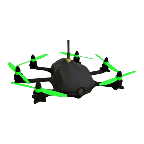
TBS GEMINI Mini
FPV Hex
Miniature hexacopter for fast
FPV flight and multirotor racing
Revision 2014-12-02
The TBS GEMINI is the latest generation of
mini racer multirotors. Its revolutionary
design with forward tilting motors and
aerodynamic canopy as well as fully
integrated yet modular electronics turn it into a beast that will dominate any race event.
Optimize your setup for HD filming with a Mobius or as the ultimate racer. Both setups are capable of
operating on 3S and 4S setups, depending on your skill level and speed requirements. It is versatile enough
to become your take-anywhere, fly-anytime multi rotor and at the same time rip through trees and leave the
competition in the dust at races.
The frame is based on a design by award-winning pilot and one of the leading innovators in multi rotor
design, William Thielicke (aka Shrediquette). TBS added its own secret-sauce with a fully-modular, crash
friendly ESC and flight control installation. We get the best of both worlds: a tightly integrated component
layout that optimizes weight efficiency, but also repair-friendliness in case of crashes. And let's face it, these
things are made for crashing.
Assembly takes a few minutes as you add props, choose between the race and film setup and secure the
canopy. A full slew of spare parts are available to repair the hex after a crash.
Key features
•
Aerodynamic canopy for stability in forward-flight
•
Forward-tilting motors for efficient, high speed flight
•
Built-in FPV camera
•
Optional Mobius HD camera (film canopy)
•
CORE OSD/power supply with integrated current sensor
•
Ready for long range FPV
•
Stacked modular TBS 4A ESCs
•
High-quality T-motors with vibration dampening
•
4-inch propellers
•
TauLabs Quanton-based flight control
•
Crash-friendly, yet integrated layout
1
Advertisement
Table of Contents

Subscribe to Our Youtube Channel
Summary of Contents for TBS GEMINI Mini FPV Hex
- Page 1 FPV Hex Miniature hexacopter for fast FPV flight and multirotor racing Revision 2014-12-02 The TBS GEMINI is the latest generation of mini racer multirotors. Its revolutionary design with forward tilting motors and aerodynamic canopy as well as fully integrated yet modular electronics turn it into a beast that will dominate any race event.
-
Page 2: Before We Begin
Before we begin Thank you for buying a TBS product! The TBS GEMINI is a new racing multirotor aircraft from Team BlackSheep (TBS). It features the best design practices available on the market to date, providing a great flying experience and incredible FPV characteristics. -
Page 3: Specifications
25C+, max. 48(W) x 70(L) x 19(H) mm, 110 grams All-up-weight: 340 to 370 grams, fully loaded Kit contents: 1x Assembled TBS GEMINI main frame (base kit) 6x TBS BULLETPROOF 4A ESCs 1x TBS COLIBRI Flight controller 1x TBS CORE PNP25, pre-configured... - Page 4 “manual” mode. There are a lot of other interesting features. The TBS GEMINI has a two part canopy with a larger volume. This allows for using large batteries, a broader range of video transmitters and larger receivers (hence people can install the gear they want). We selected to include some very nice and light custom T-motors, these are made to precision with high quality bearings.
- Page 5 IN PACKAGE The following is included in the base TBS GEMINI kit. Replacement parts are available online, if needed. 1x Set of film canopy - top/bott. 1x Set of racing canopy - top/bott. 1x Assembled GEMINI frame 8x 4x4.5-in propellers (CW, CCW)
- Page 6 Quick Start Guide - BNF set The following steps will get you setup and ready to fly quickly. It is a condensed version intended for experienced pilots. Each step is elaborated in more detail in this manual if you are new to this. You will need to install a R/C receiver, configure the COLIBRI flight control, potentially adjust VTX frequency, insert the battery and install the propellers.
- Page 7 R/C receiver Install R/C receiver A small or micro R/C receiver will fit underneath the I/O board, with the antennae feeding down the rear arms. If the receiver is too big, mount it in the front section on top of the CORE PNP25 unit or under the frame.
- Page 8 Receiver under I/O board Be careful to cover up any exposed metal if there is a chance of short-circuiting anything on the I/O board. 1. Disconnect the red JST battery connector to the I/O board 2. Gently wiggle the front and back of the board to remove it from the sockets, be sure not to bend the pins 3.
- Page 9 5. Strip the antenna to the arms, cut a slot in the top canopy to avoid the cable from being sheared off Receiver under the frame If the receiver is long and has a slim profile (<8 mm), it will fit between the battery and the the frame. 1.
- Page 10 4. Add two foam pads and a foam sheet between the battery for protection and cushioning 5. Cut a notch in the bottom canopy for the antenna connector and antenna An alternative way to install the EzUHF Lite, is to install it under the I/O board and modify the VTX plastic support to let the PPM cable through.
- Page 11 Configure COLIBRI flight control Install drivers and software Download the TauLabs configuration software and driver for the TBS COLIBRI flight controller, from https://github.com/TauLabs/TauLabs/releases/ (OS X/Win/Linux), links at the end of the latest post. Open the TauLabs GCS software and connect a micro-USB cable to the COLIBRI board. GCS will detect the board and at the bottom of the view it should indicate that the controller is connected.
- Page 12 Next, with a new model set up on the radio and the receiver bound to the transmitter, attach the video transmitter antenna and connect a LiPo battery to the GEMINI to power the R/C receiver (USB will not provide power to the receiver). Open the “Input”...
- Page 13 You should be able to see all the stick inputs “live” and the current position of the flight mode switch under the “Flight Mode Switch Settings” tab. Because of the way the flight controller is implemented, the motors are run in reverse. This requires the mixer settings to have “reverse all motors”...
- Page 14 https://github.com/TauLabs/TauLabs/wiki/Flightmode-Settings for further details how the different flight modes behave. Set failsafe When the flight controller detects a failsafe (caused by equipment or range failure) it will turn off all the motors (sets throttle to zero). This is the safest behavior compared to potentially having settings that cause it to float off or even climb higher.
- Page 15 Install canopy brackets The frame has six embedded magnets to lock the top and bottom canopy in place. The kit includes a two metal strips which needs to be cut to length and installed with superglue (not the supplied cement glue). The final bracket should resemble a half-triangle.
- Page 16 4. Add a drop of superglue to one bracket at a time. Align it with the key markings and adjust so it is flush to the trim of the canopy. If the bracket stands out, bend it some more to minimize canopy gaps.
- Page 17 Set-up video transmitter The included TBS UNIFY 5G8 200mW video transmitter and encased cloverleaf antenna provides great range (up to 1km line-of-sight) and supports 32-channels (compatibility with Fatshark, IRC, DJI and all other brands). The 5G8 frequency band means no interference when using a 2G4 R/C transmitter. The kit comes with a VTX extension cable holder if you want to replace and use a larger VTX which does not fit the standard VTX spot.
-
Page 18: Mount Battery
Pilot camera The TBS CHIPHIP V2 600 TVL PAL pilot camera comes with a 2.8 mm lens and pre-configured to capture a bright and crisp image. No configuration required. If the image turns out to be out of focus, loosen the phillips set/grub screw on the top and turn the lens. The lens is also exchangeable to get a narrower or wider viewing angle, e.g. - Page 19 Mount Mobius HD camera - film canopy The stock setup comes prepared with a carriage for a Mobius HD camera (available separately), but it can be swapped out for a much lighter carriage to only hold the pilot camera. Coupling this with the streamlined racing canopy, makes for a serious rocket, especially on 4S! See section later in the manual for conversion specifics.
- Page 20 4. When properly positioned, the footage should not show the propellers in view (neither normal or wide-angle B lens). If you do see the propellers, ensure that the camera is fully straight and move it towards the front by a bit. Since the camera now is mounted upside-down to allow access to the control buttons, enable 180°...
-
Page 21: Install Propellers
Install propellers There are two kinds of 4x4.5-inch propellers in the kit, clockwise rotation (3x CW) and counter-clockwise rotation (3x CCW). Mounting them in the proper manner is paramount for a safe first flight. On the GEMINI arms, there are indicator showing the rotational direction for each motor and propeller. The propellers also need to be mounted with the side with the text and small prop hole facing up. - Page 22 4. Secure the propellers using the provided M4 spinners - use an Allen wrench through the small hole on the cone to tighten them properly Make sure the base of the propeller is evenly pressed against the motor bell for perfect tracking and minimum vibrations.
- Page 23 Finishing up When everything setup and configured, perform this short procedure to get into a hover. 1. Turn on the radio and video goggles 2. Put on the top canopy and attach the antenna 3. Connect the LiPo battery 4. Start the Mobius recording 5.
-
Page 24: Menu Configuration
TBS CORE The TBS CORE PNP25 included in the kit is mounted behind the pilot camera and provides voltage regulation to the video transmitter and pilot camera, in addition to an On-Screen Display (OSD) overlay for crucial flight data (mAh current consumption, battery voltage, flight timer, receiver signal). An optional TBS PNP PRO upgrade can provide additional details such a home direction, speed and location. - Page 25 Custom VTX and Camera voltages The CORE PNP comes pre-setup with 5V and 12V on the VTX and CAM ports, respectively, to support the included equipment. If you install different equipment requiring different voltages, you need to open the CORE PNP25 case and bridge the correct voltage. Failing to set the correct voltage can damage your equipment.
- Page 26 Wire Function Black +5V (leave unconnected) White RSSI signal Next, enter the CORE configuration menu and select the correct RSSI protocol type for your receiver (ANALOG or DIGITAL). The configuration will also ask you to turn on and off the transmitter to record the min. (0%) and max.
- Page 27 Upgrade to CORE PRO While the CORE PNP25 is plenty fine for the type of close range and proximity flight the GEMINI is designed for, the CORE PRO provides additional flight stats and helps you maintain a sense of direction. Upgrading to the CORE PRO requires replacing the CORE PNP25 unit, installing the current sensor and optional GPS module.
-
Page 28: Repair And Maintenance
Repair and maintenance Replace ESC 1. Remove the canopy and lift the I/O board out of its sockets 2. At the bottom of the board, there are six rows, each with six solder joints (for control, power and motor). Use the diagram below to determine the correct ESC to remove. 3. - Page 29 4. Carefully remove the ESC from its slot and replace with a new unit 5. Once the ESC is well seated, hold the ESC to be parallel to the others and re-apply solder to both sides of the ESC slot 6.
- Page 30 2. Wiggle it slightly on both ends to avoid popping it off and bending the pins 3. Replace the controller and put it back on the sockets - ensure the controller is seated properly 4. Use TauLabs GCS to configure the controller with the default TBS GEMINI settings (see below for links to the files)
-
Page 31: Replace Motor
Replace motor The design of the motor mount is made to handle a hard crash without sacrificing other parts of the frame. This means that the motor screw will break away when you have a hard crash. Additionally, the included rubber dampeners help to isolates vibrations from the propellers from the rest of the frame. -
Page 32: Replace Propeller
4. Wrap the cable around the arm and connect it to the Molex header on the frame 5. For extra protection from dirt and gravel, add a piece of black tape around the connector Replace propeller 1. Hold the motor by the bell while using an Allen wrench to remove the prop spinner 2. - Page 33 Replace camera 1. But back the lens cap to protect against scratches during the repair (to reuse the lens) 2. The flight camera is held in place with two plastic locking pins and two screws, use a screwdriver to push the center pin then the rivet on the top corners and remove the two screws on the lens...
- Page 34 3. Lift the camera straight up and out of the camera mount 4. Replace with a new camera, break away the edge tabs if needed - reverse the process Replace video transmitter 1. Remove the antenna and lift off the canopy. The stock VTX is attached to the VTX mounting bracket with double-sided adhesive foam tape.
- Page 35 4. Apply a new piece of adhesive foam tape to the VTX and align the antenna connector in the center of the frame/mounting bracket, positioned high enough for the connector to protrude through the top canopy...
-
Page 36: Common Questions
Common questions Issue: The ESCs get hot while idle Solution: This is completely normal and is part of the design. When flying, the circulation will provide adequate cooling. Issue: Motors not arming Solution: Can you go to the Flight Status page in GCS and check that the system health gadget does not show any errors. - Page 37 Custom Assembly Select canopy The difference between the top racing and film canopy is subtle, but noticeable. You can use the film canopy on the racing setup, but not the other way around. Racing canopy For racing and optimal aerodynamic flight, use the Race canopy. This drops down the pilot camera a notch and removes the Mobius HD camera carriage, making everything streamlined and light-weight with only the pilot camera and VTX antenna visible.
- Page 38 Convert to racing canopy 1. Remove the video transmitter by gently prying off the adhesive while holding onto the VTX body 2. Remove the pilot camera by pushing out the two top locking pins and removing the two screws on the lens 3.
- Page 39 4. Remove the CORE PNP25 unit, it is fastened with a adhesive foam tape 5. Use a screwdriver to unseat the four damping balls on the Mobius mounting plate 6. From the bottom side, push the five plastic locking pins and rivets of the the carriage to release it from the frame...
- Page 40 7. Continue by installing the racing camera mount to the pilot camera in the orientation shown, fasten using two locking pins and two screws, as shown 8. Position the camera over the front four holes on the frame and use four locking pins to install it - do the same for the VTX mount, use a single locking pin the fasten it...
- Page 41 9. Install the video transmitter on the new mounting bracket. Loop the CORE PNP25 cables through the holes shown and connect up the pilot camera and video transmitter. Bottom side of the frame:...
- Page 42 10. With the new carriage installed, use the light and streamlined racing canopy to finish off the conversion!
- Page 43 Film canopy The included Film canopy provides additional bulkhead and volume on the bottom of the GEMINI to facilitate a Mobius HD ActionCam. The Mobius camera is mounted on a separate camera plate which is suspended beneath the frame using damping balls.
- Page 44 Convert to film canopy 1. Disconnect the cables for the I/O board and video transmitter and untangle the battery leads from the bottom side 2. Lift out the CORE PNP25 unit from its spot. From the bottom side, use a screwdriver to push through the plastic locking pins and rivets for the camera- and video transmitter mounts 3.
- Page 45 4. Turn the frame over and position the Mobius mounting plate over the dampening balls. Use a short loop of wire to hook through the hole and pull the end of the damping ball through. 5. Put the CORE PNP25 back on the top of the frame while leaving space for the VTX and camara - route the cables as shown...
- Page 46 Bottom side of the frame: 6. Connect the pilot camera and lock it in place using two locking pins on the top two corners and two screws on either side of the lens 7. Connect the VTX and mount it with a piece of strong adhesive foam tape. Position it with the antenna connector in the center of the VTX mount and high enough to reach through the canopy.
- Page 47 8. Finish off the conversion with the film canopy!
-
Page 48: Video System
Video system Change pilot camera The supplied camera mounts supports standard 32x32 mm board cameras. There is a fair bit of depth behind the mount to allow thicker boards and cables to loop through. Change video transmitter Because of the limited space in the top canopy, you can only fit a small VTX on the allocated spot - max. dimensions can not exceed 40(H) x 35(W) x 10(D) mm. -
Page 49: Drive System
Drive system Motors Changing the motors to a different 1806 type requires that the mounting pattern and wire connection is compatible, or modified to fit. The mounting pattern on the arms will fit 22 x 22 mm motors. R/C receiver Traditional PWM receiver install It is possible to install a 5-channel receiver using individual servo cables for each channel (instead of PPM/S-BUS/D-BUS). - Page 50 2. Open TauLabs GCS, go to the “Hardware” view and change “RcvrPort” to “PWM” to enable the five inputs. Also be sure “UART2” is set to “Disabled”, as shown. Click “Save” and unplug power to reboot. 3. Now, go to the “Input” view and change the “Type” to “PWM” for all the first five channels. Or run the configuration wizard to map the receiver signals to the right controls one by one.
- Page 51 Spektrum Satellite install Using a Spektrum Satellite as a receiver makes for a very compact and neat install. ● OrangeRx R100 DSM2 satellite ● Spektrum AR6200/AR6210 DSMX satellite ● Spektrum AR9000 DSM2 satellite Spektrum AR9010AR9110 DSMX satellite ● Binding the satellite to the transmitter 1.
- Page 52 Important: The red 5V pin has been moved to the 3.3V pin - otherwise the satellite could be damaged. Configure COLIBRI Connect a LiPo battery to get power to the satellite, configure the COLIBRI to accept DSM2 (DX7) or DSMX 11-bit (DX7S, DX8, DX9) on UART2 using TauLabs GCS, as shown.
- Page 53 Flight controller Tuned PID settings To further improve how the GEMINI handles in the air you can tuned the control loop which is the backbone in the flight controller. Open “Configuration” and go to the “Stabilization” view. The second “Advanced” tab lets you tune the core parameters.
- Page 54 Altitude Hold In this mode the controller it will hold the current altitude by monitoring atmospheric pressure using the on-board barometer sensor. If your throttle stick is high the aircraft will climb and if it is low it will descend. Before enabling this mode, be sure the “Altitude Hold”...
-
Page 55: Good Practices
Good practices We have compiled a list of all of practices which have been tried and tested in countless environments and situations by the TBS crew and other experienced FPV pilots. Follow these simple rules, even if rumors on the internet suggest otherwise, and you will have success in FPV. Start with the bare essentials and add equipment one step at a time, after each new equipment was ●... - Page 56 ● Try to achieve as much separation of the VTx and R/C receiver as possible to lower the RF noise floor and EMI interference. ● Do not buy the cheapest equipment unless it is proven to work reliably (e.g. parts falling off, multitudes of bug fix firmware updates, community hacks and mods are a good indicator of poor quality and something you do NOT want to buy for a safe system).
Need help?
Do you have a question about the Mini FPV Hex and is the answer not in the manual?
Questions and answers