
Related Manuals for Sanden SD7H15

Summary of Contents for Sanden SD7H15
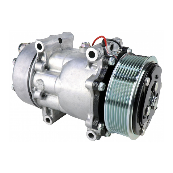
- Page 1 Sanden SD7H15 Type C Service Manual Date of Issue: July 1999 Prepared by: Sanden International (Europe) Ltd. SANDEN...
- Page 2 A/C system and/or the compressor for which this Service Manual is destined. Sanden Corporation shall neither assume responsibility nor be kept liable for any loss or damage to the human life or body and/or the property which occurs or has occurred in conducting or in relation to services carried out in accordance with or in reference to this Service Manual.
-
Page 3: Table Of Contents
Contents Description Page No. 1. Cautionary Information 2. Compressor Torque specifications 3. Service Operations – Clutch 4. Service Operations – Shaft Seal 5. Service Operations – Cylinder head SD7H15 Type C Service Manual Prepared July 1999 – Application Engineering... -
Page 4: Cautionary Information
Work in a well ventilated area. 5. Avoid use of Compressed Air Do not introduce compressed air into an A/C system due to the danger of contamination. SD7H15 Type C Service Manual Prepared July 1999 – Application Engineering... -
Page 5: Compressor Torque Specifications
High pressure relief valve 10.0±2.0 Armature dust cover 3.50±0.5 2.2 SD7H15 TYPE C PAG OIL The SD7H15 Type C compressors leave the factory production line with SP10 PAG oil. SD7H15 Type C Service Manual Prepared July 1999 – Application Engineering... -
Page 6: Service Operations - Clutch
5. Remove bearing dust cover (if present). Use caution to prevent distorting cover when removing it. Fig.1 Removal of armature retaining nut Fig.2 Slide armature up and off shaft SD7H15 Type C Service Manual Prepared July 1999 – Application Engineering... - Page 7 Service Operations - Clutch 3.2 Rotor Assembly Removal 1. Remove rotor retaining snap ring using snap ring pliers.(Fig.3) 2. Remove rotor using Sanden removing tool. (Fig.4) 3. The rotor bearing is not changeable as it is staked into position.(Fig.5) Fig.3 Remove snap ring Fig.4 Remove rotor...
- Page 8 4. Remove the shims from the shaft. Use a pointed tool and a small screwdriver to prevent the shims from binding on the shaft.(Fig.8) Fig.6 Remove clamp screw Fig.7 Remove snap ring Fig.8 Remove shims SD7H15 Type C Service Manual Prepared July 1999 – Application Engineering...
- Page 9 5. Reinstall the rotor retaining snap ring using snap ring pliers.(Fig.10) 6. Reinstall rotor bearing dust cover (if present) by gently tapping it into place. Fig.9 Installation of rotor using arbor press Fig.10 Re-install snap ring SD7H15 Type C Service Manual Prepared July 1999 – Application Engineering...
- Page 10 5. Replace armature dust cover (if used) Reapply thread lock and torque 3 bolts to 3.50±0.5N•m Fig.11 Replace shims Fig.12 Torque armature retaining nut Fig.13 Check air gap with feeler gauges SD7H15 Type C Service Manual Prepared July 1999 – Application Engineering...
-
Page 11: Service Operations - Shaft Seal
Clean out shaft seal cavity completely. Make sure all foreign material is completely removed. Fig.14 Felt ring removal Fig.15 Snap ring removal Fig.16 Shaft seal removal SD7H15 Type C Service Manual Prepared July 1999 – Application Engineering... - Page 12 (Away from the compressor body). Ensure that the snap ring is completely seated in the groove. 10. Tap new felt ring assembly into place. 11. Reinstall clutch assembly as detailed in section A. SD7H15 Type C Service Manual Prepared July 1999 – Application Engineering...
-
Page 13: Service Operations - Cylinder Head
Be careful not to disturb the valve plate to cylinder block joint if valve plate is to be left in place. If valve plate comes loose from cylinder block, proceed to section 5.2 Valve plate removal. SD7H15 Type C Service Manual Prepared July 1999 – Application Engineering... - Page 14 5. Coat head gasket with clean refrigerant oil. 6. Install head gasket over location pins, checking for correct orientation. 7. Install cylinder head. SD7H15 Type C Service Manual Prepared July 1999 – Application Engineering...
- Page 15 8. Install cylinder head bolts and tighten in a star pattern.(Fig.22) Torque first to approximately 20.0N•m, then finish by torquing to 34.0 ±5.0N•m (Fig.23) Fig.22 Torque sequence of cylinder head bolts Fig.23 Torquing cylinder head bolts SD7H15 Type C Service Manual Prepared July 1999 – Application Engineering...
- Page 16 SD7H15 Type C Service Manual Prepared July 1999 – Application Engineering...
Need help?
Do you have a question about the SD7H15 and is the answer not in the manual?
Questions and answers
My clutch has a black and a black/white wire on it. Which is the ground? I need to change plugs and my old pump had red and black wires.