
Summary of Contents for Yamatake HGC303
- Page 1 Heat Value Gas Chromatograph Model: HGC303 User’s Manual HGC000001000P CM2-HGC100-2001 First issue: Apr. 2001, Rev.12: Oct. 2004...
- Page 2 In no event shall Yamatake Corporation be liable to anyone for any indirect, special or consequential damages. The information and specifications in this document are subject to change without notice.
- Page 3 Safety Safety symbols Be sure to correctly operate the model HGC303 while strictly observing the safety precautions provided in this manual-especially the Warnings and Cautions indicated by the symbols as shown below. The descriptions of the Warning and Caution signs used in this manual are as follows.
- Page 4 NEVER open the terminal box cover while the model HGC303 is energized in a hazardous location. CAUTION Use the model HGC303 only in an ambient temperature of -10 to 50°C (14 to 122°F) CAUTION Take precautions to prevent corrosion, deformation or damage to the housing or terminal box cover.
- Page 5 EN 60079-17 Part 17: Inspection and maintenance of electrical installations in hazardous areas. EN 50281-1-2 Electrical apparatus for use in the presence of combustible dust Part 1-2: Electrical apparatus protected by enclosures -- Selection, installation and maintenance Model HGC303 - Heat Value Gas Chromatograph...
- Page 6 75K to the maximum surface temperature of the enclosure “T...°C” as marked on the apparatus, the apparatus is incapable of causing ignition of the dust layer. (T...°C is based on the maximum ambient temperature) Model HGC303 - Heat Value Gas Chromatograph...
- Page 7 • Do not open the apparatus enclosure when an explosive atmosphere is present. Figure S-1 An example of conduit seal (with stopping plug) Figure S-2 An example of conduit seals (without stopping plug) Model HGC303 - Heat Value Gas Chromatograph...
- Page 8 (2) a horizontal raceway not less than 10 ft (3.05 m) long; or (3) a vertical raceway not less than 5 ft (1.52 m) long and extending downward from the dust-ignitionproof enclosure. • Seals are not required to be explosionproof. Model HGC303 - Heat Value Gas Chromatograph...
- Page 9 • All boxes and fittings must be dusttight. 5.2 Sealing • Sealing means are not required. 6. Class III, Division 2 locations 6.1 Wiring methods • Wiring methods must comply with 5.1. 6.2 Sealing • Sealing means are not required. Model HGC303 - Heat Value Gas Chromatograph...
- Page 10 Safety Yamatake Corporation viii Model HGC303 - Heat Value Gas Chromatograph...
-
Page 11: Table Of Contents
Table of Contents Chapter 1: Introduction 1-1: Definition of terms ..................1-1 1-2: General ......................1-3 1-3: Model HGC303 measuring system ............... 1-4 1-4: Model HGC303 Structure................1-5 1-5: Fieldbus communication system..............1-6 Chapter 2: Installation 2-1: Unpacking and storing .................. 2-1 2-2: Selecting an interface and installation ............ - Page 12 3-5-7: Main display panels of HGM (GPA)..........3-60 3-5-8: Report (GPA)................... 3-65 Chapter 4: Maintenance 4-1: Checking and changing the carrier gas ............4-1 4-2: Checking and changing the filters in model HGC303 ........4-1 4-3: Overhaul ....................... 4-1 Chapter 5: Troubleshooting Appendix GPA calculation....................
- Page 13 Figure 2-8 Example of cable finish..............2-13 Figure 2-9 Model HGC303 dimension ..............2-15 Figure 2-10 Example of model HGC303 installation with mounting bracket..2-16 Figure 2-11 Piping location ................... 2-17 Figure 2-12 Wiring location ................... 2-19 Figure 3-1 Leak check ..................3-3 Figure 3-2 Model HGC303-HGM connection example ........
- Page 14 Table 2-5: Wiring description................. 2-19 Table 3-1 Gas specifications ................3-1 Table 3-2 The procedure to start up the model HGC303 system......3-2 Table 3-3 Model HGC303 leak test procedure ............. 3-3 Table 3-4 Stopping model HGC303 operation ............. 3-4 Table 3-5 Main menu description .................
-
Page 15: Chapter 1: Introduction
Modbus signal as well as a Fieldbus signal. See the model HMU303 User's manual for more details. HGC Data Manager (Model HDM303) Model HDM303 is Modbus interface unit for model HGC303. Model HDM303 covers all the function of model HMU303. Model HDM303 also has a powerful functions. - Page 16 HGC Monitor (HGM) HGM software is provided as a standard accessory with the model HGC303. The model HGC303 Monitor allows the user to con- figure and calibrate the model HGC303 as well as allowing one to monitor a heat value-trend graph.
-
Page 17: General
Introduction 1-2 : General The model HGC303 is a gas chromatograph designed to analyze natural gas and is able to transmit a process variable via a Fieldbus signal. One can easily adjust configuration data and monitor values such as the heat value by using the HGM. -
Page 18: 1-3: Model Hgc303 Measuring System
AIR/N Standard PIPE LINE Sample Gas Figure 1-1 Model HGC303 measuring system diagram CAUTION A block valve is a kind of air actuator valve. It is used mainly for the protection of the TCD and columns. It works as sample shut-off valve when the pressure of the carrier gas or air supply is lower than approximately 294 kPa. -
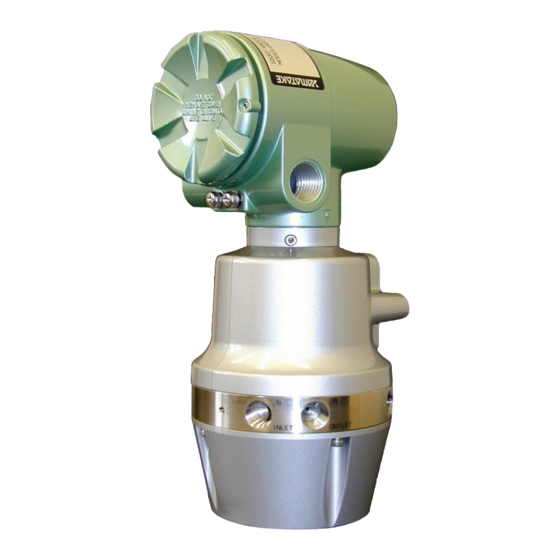
Page 19: 1-4: Model Hgc303 Structure
Manifold Oven cover HGC000004000D Figure 1-2 Main parts of Model HGC303 1 Terminal housing ..Terminal box for wiring. 2 Analyzer unit housing ...Micro valve, solenoid valve, TCD sensor are located here. 3 Manifold......Connection parts for gas inlet and outlet line 4 Oven cover ....Analyzer valve and column system are found inside the... -
Page 20: 1-5: Fieldbus Communication System
™ fieldbus Technical overview (FD-043) OUNDATION (2) Fieldbus Installation & Planning Guide (AG-165) (3) F ™ fieldbus Application Guide OUNDATION 31.25kbit/s Wiring and Installation (AG-140) (4) F ™ fieldbus Application Guide OUNDATION 31.25kbit/s Intrinsically Safe Systems (AG-163) Model HGC303 - Heat Value Gas Chromatograph... -
Page 21: Chapter 2: Installation
2-1 : Unpacking and storing Unpacking the model HGC303 Your model HGC303 is a precision instrument and should be handled with care to pre- vent any damage to it or breaking it. After unpacking the model HGC303, verify that the following items are included:... - Page 22 Yamatake representative. When making an inquiry, make sure to provide the model number and product number of your model HGC303. HGC000002000P Model HGC303 - Heat Value Gas Chromatograph...
- Page 23 - indoor at storage temperature (-40 to 70°C); humidity (up to 95%RH) - in a place safe from vibration or shock. - in the same packing as it was shipped in. Model HGC303 that has been used should be stored by following procedures below. Step Action Makes sure no process gas remains in the model HGC303.
-
Page 24: 2-2: Selecting An Interface And Installation
When connecting the model HFA100 to a USB port, an installation wizard will appear on your screen. Follow the instructions that the installation wizards give you. You will be asked for your CD-ROM that came with the model HGC303 where you should select the folder “HFBADRV”. (Once the file ‘HFBADRV’ is installed, cannot be uninstalled.) -
Page 25: Figure 2-1 Hfa Configuration Initial Display
Connect the model HFA100 to the PC, and then start HFA Config.exe (Default directory: C:\Program file\HGM), which is in the HGM folder. A dialog box like that shown in Figure 2-1 will appear. Figure 2-1 HFA configuration initial display Model HGC303 - Heat Value Gas Chromatograph... -
Page 26: Figure 2-2 Model Hfa100 Operation Check Display
Figure 2-2 Model HFA100 operation check display Default Setting PD_TAG: HFA100 Node Address: 0×FC Device Class: Basic Device This completes your model HFA100 installation. Refer to “3-3 : HGM operation” when using the model HFA100 connected to a HGM. Model HGC303 - Heat Value Gas Chromatograph... - Page 27 However, when changing the settings, have a thor- ough understanding of the parameters beforehand. * “Fieldbus device configuration” is only for authorized service personnel. If the “Fieldbus device configuration” button is clicked, shutdown at once and then restart “HFA Config.exe”. Model HGC303 - Heat Value Gas Chromatograph...
-
Page 28: 2-2-2: Installing The National Instruments Fieldbus-Pc Interface
3) PCMCIA-FBUS Cable (1 port) 4) Documentation Kit (2) ISA board Type Product name: AT-FBUS (1 port) Model number: 777281-01 Includes: 1) Fieldbus Interface ISA board 2) NI-FBUS Communication Manager Software 3) Documentation Kit Model HGC303 - Heat Value Gas Chromatograph... -
Page 29: 2-3-1: Computer System Requirements
Before installing the HGM, Windows 98 / Me / NT / 2000 / XP must be installed and running as an operating system on your computer. ~Note Install the latest service pack of Windows. Model HGC303 - Heat Value Gas Chromatograph... -
Page 30: Figure 2-3 Setup Message
Exit Setup Figure 2-4 HGM installation location Default directory: C:\Program Files\hgm If you want to use another drive or directory, select an optional drive or directory by pressing the [Change Directory] button. 2-10 Model HGC303 - Heat Value Gas Chromatograph... -
Page 31: Figure 2-5 Group Name
If a version conflict message appears, select [Yes]. Installation is complete once the message below appears on your screen. HGM000005000S Figure 2-6 Complete installation Refer to “3-3 : HGM operation” on page 3-4. Model HGC303 - Heat Value Gas Chromatograph 2-11... -
Page 32: 2-4: Fieldbus Installation
Various types cables are usable for fieldbus. Type A is the preferred fieldbus cable. Yamatake recommends type A as the fieldbus cable to use. The table below describes the type of cable and its maximum length, which is speci- fied in the IEC 1158-2/ISA S50.02 Physical Layer Standard. - Page 33 The terminator impedance value shall be 100 ohm +/- 2% over a frequency range of 7.8 kHz to 39 kHz. The model HGC303 and model HMU303 have a terminator at the fieldbus connection port therefore an additional terminator is not required.
-
Page 34: 2-4-2: Fieldbus Wiring
Never connect a terminator between the signal (+ or -) and cable shield. Heat shrink sleeve Twiseted pair wire Jacket Overall shield Shield wire Wire terminal Figure 2-8 Example of cable finish 2-14 Model HGC303 - Heat Value Gas Chromatograph... -
Page 35: 2-5: Model Hgc303 Installation
A sheltered location conforming to class C as defined by IEC654-1. This is so to protect the model HGC303 from direct sunlight, wind, and rain. Select a site that allows for the installation of a housing structure or protective pan- els. -
Page 36: 2-5-2: Model Hgc303 Dimensions
Installation Yamatake Corporation 2-5-2 : Model HGC303 dimensions The dimensions of the model HGC303 are given below. [Unit: mm (inch)] 115 (4.5) 77 (3.0) 100 (3.9) Figure 2-9 Model HGC303 dimension A workspace should be selected taking into consideration facilitation of wiring, pip- ing, and maintenance. -
Page 37: 2-5-3: Model Hgc303 Installation Example
Yamatake Corporation Installation 2-5-3 : Model HGC303 installation example Install the model HGC303 as shown in following diagrams. The weight of the model HGC303 with mounting bracket is 5 kg / 11 lbs. 2in. pipe Hexagon head bolt Mounting bracket... -
Page 38: 2-5-4: Model Hgc303 Piping
Process gas inlet INLET Inlet for introducing the process gas. Process gas outlet OUTLET Outlet for process gas. Outlet for mixture of measured gas and carrier gas Measured gas outlet TCD-VENT after analysis. 2-18 Model HGC303 - Heat Value Gas Chromatograph... -
Page 39: Table 2-4: Gas Specifications
400 ± 50 kPa Valve operating Helium, Air, 99.99% or higher Nitrogen (58 ± 7 psi) 50 - 490 kPa (7 - 71 psi) Process gas Natural gas at flow meter inlet Model HGC303 - Heat Value Gas Chromatograph 2-19... -
Page 40: 2-5-5: Model Hgc303 Wiring
FB terminal (+) No connection Terminator (-) Terminator (+) Internal GND External GND ² ~Note Yamatake recommends cable of conductor cross-sectional area 2 (mm ) or equivalent for power supply connection and GND connection. 2-20 Model HGC303 - Heat Value Gas Chromatograph... - Page 41 Yamatake Corporation Installation WARNING Only a 24V DC supply may be used to operate the model HGC303. Model HGC303 - Heat Value Gas Chromatograph 2-21...
- Page 42 Installation Yamatake Corporation 2-22 Model HGC303 - Heat Value Gas Chromatograph...
-
Page 43: Chapter 3: Operation
50 ± 20 ml/min. 3-1-2 : Piping leak check Before starting up the model HGC303, conduct a leak test to verify there is no leakage of gas from the piping connection. A leak test using soap bubbles will be sufficient. -
Page 44: Table 3-2 The Procedure To Start Up The Model Hgc303 System
After turning on the power, allow 2 hours for the device to warm up. The carrier gas pressure SP and oven temperature SP have already been factory set in the model HGC303, therefore, the user doesn't have to worry about setting this data. Carrier gas pressure SP: less than 300 kPa (43.5 psi) (SP differs with each model HGC303) Oven temperature SP: 58°C (136.4°F) -
Page 45: 3-1-4: Model Hgc303 Leak Check
Operation 3-1-4 : Model HGC303 leak check After turning the model HGC303 on, conduct a leak test to verify that there is no leakage of gas from the model HGC303. The following procedures are for a simple leak test for the carrier gas line. -
Page 46: 3-2: Stopping The Model Hgc303
Turn off the model HGC303 power. Shut off the carrier gas line. Shut off the valve operating gas line. Refer to “ Storing the model HGC303” on page 2-2 when removing the model HGC303 from the field. 3-3 : HGM operation Introduction The functions of the HGM are described in this chapter. -
Page 47: 3-3-1: Getting Started With Model Hfa100
HGM connection is possible at any location along the FB line. Connect the HGM as shown in the picture below. Figure 3-2 Model HGC303-HGM connection example (combination of model HGC303, model HGU303 and model HFA100) Refer to the model HMU303 user’s manual regarding the details of each part of the model HMU303. -
Page 48: Main Menu
Starting up the HGM with model HFA100 The procedure to start the HGM up are given below. 1. Make sure that both the model HGC303 and the model HMU303 are running normally. 2. Prepare a personal computer, which has the HGM installed. - Page 49 User's manual Quit User's mode [HGM.exe] Heat value & Total raw conc. Monitoring Chromatogram (Offline) Carr.press.& Oven temp. Data load Print out Report Print out Next, proceed to “3-3-3 : HGM Main menu”. Model HGC303 - Heat Value Gas Chromatograph...
-
Page 50: Getting Started With Pcmcia-Fbus
HMU000002000P HMU000003000P Figure 3-3 Model HGC303-HGM connection example (combination of model HGC303, model HMU303 and laptop PC) Refer to the model HMU303 user's manual regarding the details of each part of the model HMU303. Model HGC303 - Heat Value Gas Chromatograph... - Page 51 Starting up the HGM with PCMCIA-FBUS The procedure to start the HGM up are given below. 1. Make sure that both the model HGC303 and the model HMU303 are running normally. 2. Prepare a personal computer, which has the HGM installed.
- Page 52 (12) Click [OK] (close Interface Configuration Utility). 8. Run the [NIFB.exe] program. If the NIFB software is running, [NI-FB] icon will automatically be displayed on the taskbar. Rung the [hgmdrv.exe] program. 9. Run the [hgm.exe] program. 3-10 Model HGC303 - Heat Value Gas Chromatograph...
- Page 53 [HGC] appears in Close [NI-FBUS dialog] [NI-FBUS dialog] Close [NI-FBUS dialog] HGM000008000D CAUTION When the HGM is connected to the model HGC303, confirm that NI-FB and hgm- drv.exe are always functioning properly. Model HGC303 - Heat Value Gas Chromatograph 3-11...
- Page 54 User's mode [HGM.exe] Heat value & Total raw conc. Quit Monitoring Chromatogram [hgmdrv.exe] Carr.press.& Oven temp. Quit [NI-FB.exe] Data save Print out Manual calibration Calibration Auto calibration Report Print out Field work HGM000006001D 3-12 Model HGC303 - Heat Value Gas Chromatograph...
- Page 55 Start [HGM.exe] : Main menu Main menu User's manual Quit User's mode [HGM.exe] Heat value & Total raw conc. Monitoring Chromatogram (Offline) Carr.press.& Oven temp. Data load Print out Report Print out Model HGC303 - Heat Value Gas Chromatograph 3-13...
-
Page 56: Set Up Hgm Display
Monitoring heat value trend graph and chromatogram. You can also perform calibrations using this mode. User's manual Model HGC303 user's manual reference (pdf file). Configuration mode The model HGC303 can be configured from here can be done here. Quit Exit from the HGM application. 3-14... -
Page 57: 3-3-4: Set Up Hgm
Yamatake Corporation Operation 3-3-4 : Set up HGM Before the HGM can communicate with the model HGC303, an initial setup must be performed as follows. a. Initial screen b. After clicking on [Change password]) c. Normalization method setting Figure 3-5 Set up HGM display... -
Page 58: Table 3-6 Set Up Hgm Description
See section “3-3-8 : Configuration mode” to set HGM to HGC. Follow the procedures given below in order for the HGM to communicate with the model HGC303. 3-16 Model HGC303 - Heat Value Gas Chromatograph... -
Page 59: Table 3-7 Set Up Online Mode
[Analyzer Status] Select [HGC] in Analyzer Status If [HGC] cannot be selected from the pull-down menu, click on [Refresh]. The HGM searches for the model HGC303 again along the Fieldbus line. [Data saving interval] Select “data saving interval” from pull-down menu;... -
Page 60: Table 3-8 Analyzer Status And Available Functions
Date and time, PV17, PV18 No.3 (1 hour =720 data) 4000/720=5.5 hours Text files (.hv1 and. cv1) are saved at the same time with the save function, which is described in Table 3-12 No.3. 3-18 Model HGC303 - Heat Value Gas Chromatograph... -
Page 61: Figure 3-6 Example Of Saved Data Files (.Hv1)
4 Select [All files] in “Files of type”. 5 Select a saved file, then click [open]. 6 Follow the messages that come up on screen. (Click [Comma] at “delimiters”.) HGM000011000S Figure 3-6 Example of saved data files (.hv1) Model HGC303 - Heat Value Gas Chromatograph 3-19... - Page 62 (2) Analysis data (2001/07/25 19:00-2001/07/25 23:59) is saved at 2001/07/26 0:00 Saved file names: 010725as.hv1, 010725as.cv1, 010725as.sv1. “as” stands for auto saving. HGM000012000D (3) Analysis data (2001/07/26 0:00-2001/07/26 23:59) is saved at 2001/07/27 0:00. Saved file names: 010726as.hv1, 010726as.cv1, 010726as.sv1 3-20 Model HGC303 - Heat Value Gas Chromatograph...
- Page 63 Yamatake Corporation Operation (4) Auto saving is performed daily. HGM000013000S Model HGC303 - Heat Value Gas Chromatograph 3-21...
-
Page 64: 3-3-5: User's Mode Menu And Commands
Top (blue) This graph shows heat value and the total of raw concentration Center (white) Chromatogram Bottom (red) This graph shows carrier gas pressure and oven temperature Right panel Process gas analysis data 3-22 Model HGC303 - Heat Value Gas Chromatograph... -
Page 65: Table 3-11 Description Of The Indication Panel
Return to [latest] to monitor the latest chromatogram. Auto reload function starts again. [Field work] Model HGC303 holds outputs to the host control system during field maintenance. Click on [Field work] then [ON], to set the holding time to [24hrs]. [Field work] button blinks while performing fieldwork. -
Page 66: Figure 3-8 Trend Graph Of Scv And The Total Concentration (Raw)
Online: Date and time of the latest data (data is reloaded every 5 min.) Offline: Date and time of when the data was saved. * In case of Windows 98 or Me, data are also saved in C:\My documents\MyHGC. 3-24 Model HGC303 - Heat Value Gas Chromatograph... -
Page 67: Figure 3-9 Trend Chromatogram (Online)
Offline: Date and time of when the data was saved. Status bar (Online) Status bar range: 5minutes Chromatogram data is updated every 5minutes. * In case of Windows 98 or Me, data are also saved in C:\My documents\MyHGC. Model HGC303 - Heat Value Gas Chromatograph 3-25... -
Page 68: Figure 3-10 Zoom Box
Operation Yamatake Corporation Zoom function (2 × Click on a peak of interest to get a detailed view (display only). Figure 3-10 Zoom box 3-26 Model HGC303 - Heat Value Gas Chromatograph... -
Page 69: Figure 3-11 Trend Graph Of Carrier Pressure And Oven Temp. Control
Online: Date and time of the latest data Offline: Date and time of when the data was saved. * In case of Windows 98 or Me, data are also saved in C:\My documents\MyHGC. Model HGC303 - Heat Value Gas Chromatograph 3-27... -
Page 70: Figure 3-12 User Report Entry Form
~Note File name extension of an user report is .cg1 (same as chromatogram). ~Note When you want to save report data, save either the report or the chromatogram. The chromatogram file (.cg1) includes the report data. 3-28 Model HGC303 - Heat Value Gas Chromatograph... -
Page 71: Figure 3-13 User Report
Inferior Calorific Value (ICV) 35.217 MJ/m3 35.299 MJ/m3 Density 0.7569 kg / m3 0.7586 kg / m3 Relative density 0.6179 0.6191 Wobbe Index 49.636 MJ/m3 49.705 MJ/m3 Compressibility Factor 0.9977 Figure 3-13 User report Model HGC303 - Heat Value Gas Chromatograph 3-29... -
Page 72: Table 3-15 Description Of User Report
Gas Analysis by model PV1 -11 outputs data from model HGC303 HGC303 HGC Outputs Configura- Display of model HGC303 configuration data (PV12 - tion data Heatvalue Calculation by All heat value data is calculated by the HGM and is dis- played. -
Page 73: 3-3-8: Configuration Mode
Yamatake Corporation Operation 3-3-8 : Configuration mode Various configurations of the model HGC303 and the HGM can be made in this mode. Click on [Configuration mode] in the main menu. The following screen will appear after entering the password. Figure 3-14 Configuration mode display... -
Page 74: Table 3-16 Description Of Configuration Mode Display
HGC (version 3.0 or later) and HDM (version 2.30 or later) combination. Download to HGC All configured data are downloaded to the model HGC303 by clicking on this button. Return Menu Exit from configuration mode. - Page 75 If the detected value < low cut off value, the output will be transmitted as 0 mol%. (1-2) % DEV RF limit: See “Calibration procedure” on page 3-41 for details Each RF %dev limit can be set independently. Default values are as follows: Model HGC303 - Heat Value Gas Chromatograph 3-33...
-
Page 76: Table 3-17 Possible Configurations Of Pv12-20
ICV (ideal) (MJ/m3) Following setting is available for application of HGC (version 3.1 or later), HGM (version 4.70 or later) and HDM (version 2.40 or later) combination.or ICV(real)(kJ/m3)or ICV(ideal)(kJ/m3)or ICV(real)(kWh/m3)or ICV(ideal)(kWh/m3) 3-34 Model HGC303 - Heat Value Gas Chromatograph... - Page 77 Yamatake Corporation Operation Table 3-17 Possible configurations of PV12-20 PV20 Relative density (real) [default] or Relative density (ideal) or Helium (normalized) Model HGC303 - Heat Value Gas Chromatograph 3-35...
- Page 78 ISO. However, these items can be viewed in the ISO mode. The circled items can be selected in GPA mode. If you want to change to GPA mode, refer to “3-3-4 : Set up HGM” on page 3-15. 3-36 Model HGC303 - Heat Value Gas Chromatograph...
- Page 79 • an average of n- and i-C6H14 • 47/35/17 • 50/50/0 • 50/25/25 • 57/28/14 • other value ~Note If [Other value] is selected, the following screen will appear. Input the each value for C6+’s physical constant. Model HGC303 - Heat Value Gas Chromatograph 3-37...
- Page 80 (default) and download to HGC to inactivate the multi stream function. When you use HGC with multi-stream function, please select “Use multi-stream function” and download to HGC to activate the multi stream function. 3-38 Model HGC303 - Heat Value Gas Chromatograph...
-
Page 81: 3-3-9: Hgm Shut Down
Click on [Quit] Click on upper right corner ''X'' and [Yes] in [hgmdrv.exe] Double-click on the [NIFB] icon in the task bar. Click on upper right corner ''X'' and [Yes] in [NIFB.exe] Model HGC303 - Heat Value Gas Chromatograph 3-39... -
Page 82: 3-4-1: Calibration Gas Requirement
3 At a calibration interval decided by the user. (Recommended calibration cycle is every 6 months.) 4 After the model HGC303 has been repaired or its parts have been replaced. 3-4-1 : Calibration gas requirement It is imperative that the composition of the calibration gas should resemble the process gas. -
Page 83: 3-4-2: Calibration Procedure
Yamatake Corporation Operation 3-4-2 : Calibration procedure The model HGC303 has two calibration methods. Each calibration procedure is described below. Manual calibration Manual calibration procedure is as follows: Manual calibration Online HGM User’s mode Change the inlet gas from sample gas to calibration gas... - Page 84 (3) Auto calibration will start on the day after the setting date. (4) Model HGC303 holds the process variables to host control system during [Hold time]. The model HGC303 discerns whether a new calibration should be performed or not by using an RF (response factor) during auto calibration. 3-42...
- Page 85 ------------------------------------- RF% DEV = % DEV RF Limit The model HGC303 automatically calculates a “RF% DEV” and decides whether the value is smaller than the “% DEV RF Limit” or not. |RF% DEV| ≤ “%DEV RF Limit” => “OK“ |RF% DEV| > “%DEV RF Limit” => “NG“...
-
Page 86: Table 3-19 Example Of Calibration Action
(2) Only the checked components in calibration box are recognized and judged. Refer to No.11 on “Table 3-20 Calibration factor setting” on page 3-46 for details on the check box of each component. The next section describes each function in the calibration panel 3-44 Model HGC303 - Heat Value Gas Chromatograph... -
Page 87: 3-4-3: Calibration Function
3-4-3 : Calibration function Click on the [calibration] icon in User's mode. The calibration setting panel (Refer to “ Indication panel” on page 3-23) will then appear. Figure 3-15 Calibration setting panel Model HGC303 - Heat Value Gas Chromatograph 3-45... -
Page 88: Table 3-20 Calibration Factor Setting
Click on [download] and the present time will be downloaded to the model HGC303. If the model HGC303 is turned off, the time setting will be reset to [0:00]. Please set the time again before performing auto calibration. -
Page 89: 3-4-4: Description Of Component Data Table
Cal. Gas Conc The component’s concentration in the cylinder for calibration New PH Peak height of the last calibration Old RF Last valid response factor New RF Response factor of the last calibration Model HGC303 - Heat Value Gas Chromatograph 3-47... -
Page 90: Figure 3-17 Preview Screen Of Report
New RF will be used as the response factor. If an NG message appears, no components will be calibrated and the Old RF will be used as the response factor and the model HGC303 will transmit an “RF error” to the host control system via the model HMU303. -
Page 91: 3-4-6: Calibration Methods
Yamatake Corporation Operation 3-4-6 : Calibration methods The model HGC303 has two-calibration methods, manual and automatic. Manual calibration Table 3-22 Manual calibration procedure Step Action Select [Manual calibration]. Recall the saved calibration data or input concentration of each com- ponent manually. -
Page 92: Table 3-23 Operating Auto Calibration Procedure
Auto calibration Table 3-23 Operating auto calibration procedure Step Action Set the model HGC303 Time Adjusting to the present time. Select [Auto calibration]. Choose a [Time], [Interval], [Hold time] (Refer to “Table 3-20 Calibration factor setting” on page 3-46.) Recall the saved calibration data or input concentration of each compo- nent manually, then check the small box. -
Page 93: 3-5: Gpa Mode
(3) If necessary, click on [Extended setup >>], and select “Normalization method”. (4) Configure the other values such as “Data Saving interval”, and then click on [OK]. The exchanging procedure is then completed. Model HGC303 - Heat Value Gas Chromatograph 3-51... -
Page 94: 3-5-2: Data Save
3-5-3 : Data edit The procedure to edit data is the same as for ISO mode.(Refer to “3-3-4 : Set up HGM” on page 3-15) Figure 3-20 An Example of saved data files (.hv2) 3-52 Model HGC303 - Heat Value Gas Chromatograph... -
Page 95: Table 3-24 The Contents Of Each Line Of .Hv2
Data are saved using the extensions .hv2, .cv1 and .sv2 instead of .hv1, .cv1 and .sv1. The configuration mode for the GPA mode is described next. Make sure that configuration mode has been set properly. Model HGC303 - Heat Value Gas Chromatograph 3-53... -
Page 96: 3-5-5: Configuration Mode
Operation Yamatake Corporation 3-5-5 : Configuration mode Numerous configurations of the model HGC303 and the HGM can be done in this mode. Click on [Configuration mode] from the main menu. The following screen appears after entering the password. Figure 3-21 Configuration mode display (GPA) -
Page 97: Figure 3-22 Output Configuration Panel (Gpa)
3.0 or later) and HDM (version 2.30 or later) combina- tion. Download to HGC All configured data are downloaded to the model HGC303 by clicking on this button. When the message appears, download operation has been successfully completed. Return Menu Exit from Configuration mode. - Page 98 Net HV (dry) (BTU/lbm) PV20 Real Relative Density (dry gas) [default] or Real Relative Density (sat gas) or Ideal Relative Density (dry gas) or Ideal Relative Density (sat gas) or Specific Heat K 3-56 Model HGC303 - Heat Value Gas Chromatograph...
- Page 99 Select a value to be used as C6+'s physical constant. • 47/35/17 [Default] • 50/50/0 • 50/25/25 • 57/28/14 • Other value ~Note If [Other value] is selected, the following screen will appear. Input each value for C6+'s physical constant. Model HGC303 - Heat Value Gas Chromatograph 3-57...
- Page 100 “ (5) Normalization method configuration” on page 3-38. (6) Multi-stream setting ~Note *These configuration methods are same as those for ISO mode. Refer to “ (6) Multi-stream function setting” on page 3-38. 3-58 Model HGC303 - Heat Value Gas Chromatograph...
-
Page 101: 3-5-6: User's Mode (Gpa)
Top (blue) Graph to monitor heat value and the total of raw concentration Center (white) Chromatogram Bottom (red) Graph to monitor carrier gas pressure and oven temperature Right panel Process gas analysis data Model HGC303 - Heat Value Gas Chromatograph 3-59... -
Page 102: Table 3-28 The Difference Between Iso And Gpa Mode In User's Mode
Refer to the next Calculated Value Real or Ideal CV page. Oven temperature Unit: degree C Unit: degree F Carrier gas pressure Unit: kPa Unit: psi Other function ISO and GPA use the same function. 3-60 Model HGC303 - Heat Value Gas Chromatograph... -
Page 103: Table 3-29 Indication Panel Description (Gpa)
Return to [latest] to monitor the latest chromatogram. Auto reload function starts again. [Field work] The model HGC303 holds outputs to the host control system during field mainte- nance. Click on [Field work] then [ON], to set the holding time to [24hrs]. [Field work] button blinks while performing fieldwork. - Page 104 Gallon per 1000CF iC5+ Real WI (dry) Real Wobbe Index (dry) Reid Vapor Pressure Real WI (sat) Real Wobbe Index (sat) Refer to the appendix for the calculation formula for each value. 3-62 Model HGC303 - Heat Value Gas Chromatograph...
-
Page 105: Figure 3-24 Btu Trend Graph And The Total Of Raw Concentration
Online: Date and time of the latest data (data is reloaded every 5 min.) Offline: Date and time of when the data was saved. * In case of Windows 98 or Me, data are also saved in C:\My documents\MyHGC. Model HGC303 - Heat Value Gas Chromatograph 3-63... -
Page 106: Figure 3-25 Trend Chromatogram (Online)
Online: Date and time of the latest data (data is reloaded every 5 min.) Offline: Date and time of when the data was saved. * In case of Windows 98 or Me, data are also saved in C:\My documents\MyHGC. 3-64 Model HGC303 - Heat Value Gas Chromatograph... -
Page 107: Figure 3-26 Trend Graph Of Carrier Pressure And Oven Temp. Control
Online: Date and time of the latest data. Offline: Date and time of when the data was saved. * In case of Windows 98 or Me, data are also saved in C:\My documents\MyHGC. Model HGC303 - Heat Value Gas Chromatograph 3-65... -
Page 108: 3-5-8: Report (Gpa)
Operation Yamatake Corporation 3-5-8 : Report (GPA) Figure 3-27 Report entry form (GPA) 3-66 Model HGC303 - Heat Value Gas Chromatograph... -
Page 109: Figure 3-28 User Report (Gpa Mode)
Yamatake Corporation Operation Figure 3-28 User report (GPA mode) Model HGC303 - Heat Value Gas Chromatograph 3-67... - Page 110 Operation Yamatake Corporation 3-68 Model HGC303 - Heat Value Gas Chromatograph...
-
Page 111: Chapter 4: Maintenance
4-3 : Overhaul The model HGC303 analyzer part requires an overhaul at least every 3.5 years. Overhaul is to be done at a Yamatake technical center listed at the back of this manual. Model HGC303 - Heat Value Gas Chromatograph... - Page 112 Maintenance Yamatake Corporation Model HGC303 - Heat Value Gas Chromatograph...
-
Page 113: Chapter 5: Troubleshooting
HGC303 is running. Click on the error box on the HGM screen to get more detailed information regarding the error. Table 5-1 shows the self-diagnostic functions of the model HGC303. Table 5-1 Model HGC303 self-diagnostics Error... - Page 114 HGC (version 3.1 or later), HGM (version 4.70 or later) and HDM (version 2.40 or later) combination. ** This error will occur during HGC start up. Model HGC303 - Heat Value Gas Chromatograph...
-
Page 115: Appendix
Appendix GPA calculation Description of normalization method The model HGC303 has two kinds of normalization methods. One is the Standard normalization method, and the other is the Methane normalization method. Normalization method is used to derive each component's normalized concentration from un-normalized components' concentration. -
Page 116: Table A-1 An Example Of The Calculated Normalized Concentration
* GHV: Gross Heating Value (British Thermal Unit / Cubic Foot) Decide which normalization method should be selected, and configure it to the model HGC303 at the configuration mode. In addition, don't forget to setup it at the [Setup HGM] screen for HGM. -
Page 117: Formulas
10) Wobbe index (dry) 11) Wobbe index (sat) 12) Gallons per thousand cubic feet (GPM) 13) Reid vapor pressure 14) Weight fraction 15) Liquid volume fraction 16) Specific Heat K Base temperature: 60°F. ~Note Model HGC303 - Heat Value Gas Chromatograph... - Page 118 Compressibility factor (dry) is calculated using the following formula. × × Z (dry) = 1 PB – ∑ where, PB = Base pressure = summation factor at 60°F Model HGC303 - Heat Value Gas Chromatograph...
- Page 119 = liquid density for component i 8) Gas density: GD [lb/1000CF] × × --------------- - G Density air 14.696 9) Liquid density: LD [lb/gal] × × --------------- - ∑ 14.696 where, (LD)i = liquid density for component i Model HGC303 - Heat Value Gas Chromatograph...
- Page 120 = Vapor pressure at 100°F for component i 14) Weight fraction × -------------------------- - × ∑ where, Mi = Molar mass for component i 15) Liquid volume fraction ti ( ) ⁄ ------------------------------ - ⁄ ∑ Model HGC303 - Heat Value Gas Chromatograph...
-
Page 121: Table A-2 Physical Constants Of Selected Hydrocarbons And Non-Hydrocarbons
Constants are based on GPA2145-03, at base pressure 14.696psia, temperature 60°F GPA2145-03 constants are used for HGC (version 3.0 or later) and HGM (version 4.60 or later). GPA2145-00 constants are used for HGC (version earlier than 3.0) and HGM (version earlier than 4.60). Model HGC303 - Heat Value Gas Chromatograph... -
Page 122: Iso Calculation
Appendix Yamatake Corporation ISO calculation Description of normalization method Model HGC303 has four kinds of normalization methods for ISO calculation. These are Standard normalization, Methane normalization, Helium (variable) normalization and Helium (constant) normalization. You can select one type of normalization. - Page 123 ISO calculation of Calorific value, density, relative density, Wobbe index and compression factor will be calculated using PV1-PV11(normalized) and Helium (normalized). 4 Helium (constant) normalization method Model HGC303 calculates the normalized concentration using total raw and Helium concentration by following formula. Helium Fixed value is used for Helium.
-
Page 124: Formulas
Real gas inferior calorific value, ICV (real) = ICV (ideal) / Zmix where, = mole fraction for component j Hloj = ideal inferior calorific value for component j, at (t1/t2) (ISO6976 Table 5) A-10 Model HGC303 - Heat Value Gas Chromatograph... - Page 125 6) Wobbe Index (MJ/m Ideal gas Wobbe index, Wobbe index (ideal) = SCV (ideal) / sqrt (Relative density (ideal)) Real gas Wobbe index, Wobbe index (real) = SCV (real) / sqrt (Relative density (real)) Model HGC303 - Heat Value Gas Chromatograph A-11...
-
Page 126: List Of Replacement Parts
Gland Screw 397-205-100 Terminator 80344288-001 Tag Number Plate with Screws 80344295-001 Gas Connection Membrane Filters with O-Rings 80343296-001 Seal Plugs (NPT1/4) 80253894-029 Vent Plug (NPT1/4) 80344292-001 Oven Cover Assembly 80344297-001 Mounting Bracket 80279919-008 A-12 Model HGC303 - Heat Value Gas Chromatograph... -
Page 127: Drawings
Yamatake Corporation Appendix Drawings HGC00 Model HGC303 - Heat Value Gas Chromatograph A-13... - Page 128 Appendix Yamatake Corporation A-14 Model HGC303 - Heat Value Gas Chromatograph...
- Page 129 Document Number: CM2-HGC100-2001 Document Name: Heat Value Gas Chromatograph Model: HGC303 User’s Manual Date: Apr. 2001 (First issue) Oct. 2004 (Rev. 12) Issued/Edited by: Yamatake Corporation...
- Page 130 Savemation Saving through Automation Totate international Building 2-12-19 Shibuya Shibuya-ku, Tokyo 150-8316 Japan Tel : 81-3-3486-2310 Fax : 81-3-3486-2593 http://www.yamatake.com/ This has been printed on recycled paper.
Need help?
Do you have a question about the HGC303 and is the answer not in the manual?
Questions and answers