
Subscribe to Our Youtube Channel
Summary of Contents for Observator Instruments OMC-131
- Page 1 OMC-131 True wind display Meteorological Applications Installation & technical users’ manual Version 1.14 TDC April 2017 updated to firmware v3.5...
-
Page 2: Table Of Contents
Users’ manual OMC-131 True wind display Index INDEX .............................. 2 1. GENERAL ........................... 4 2. INSTALLATION .......................... 6 2.1. M ............................6 ECHANICAL 2.2. E ............................. 6 LECTRICAL 2.2.1 General system layout ........................6 2.2.2 Power supply settings ........................7 2.2.3 Connections ............................ - Page 3 Users’ manual OMC-131 True wind display Version history 1.13 Correction in text on page 16: Starboard and Portside where exchanged. 1.14 Added comment page 4 concerning gust display & Gust reset description page 20. V1.14 Page 3 TDC-April-2017...
-
Page 4: General
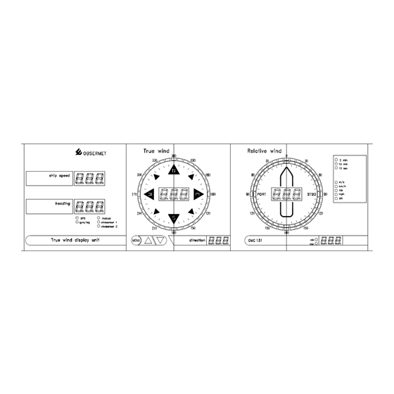
OMC-131 True wind display 1. General The Observator Instruments OMC-131 True wind display unit is specially designed for easily read out of true and relative wind information on board sea going vessels. Once again the use of the latest Observator Instruments standards in combination with a distinguished front panel, known from earlier released wind displays like OMC-139, the unit will be a breakthrough in the marine navigation market. - Page 5 RS422 NMEA-0183 (VHW) or 200 pulses per nautical mile Combined Heading - Speed : RS422 NMEA-0183 (VHW) Output Daisy chain TTY, (passive) to other Observator Instruments display units or RS422 NMEA MWV (T, R & M) RS-232 Communication & programming Connector DB9-M User interval 1 ...
-
Page 6: Installation
2. Installation 2.1. Mechanical Panel mounting of the OMC-131 display requires a panel cut-out of 435mm x 130mm. Maximum panel thickness 5 mm. Rear access must be provided, for fixing of the tightening clamps and connecting the electric cabling. The depth of the unit is 63 mm and an additional clearance of 8 mm should be allowed for the cable connections. -
Page 7: Power Supply Settings
OMC-131 True wind display 2.2.2 Power supply settings The OMC-131 will be delivered with the power supply set as required by the customer. If no power supply is mentioned in the official ordering papers the OMC-131 power supply will be set for 230 Vac. -
Page 8: Connections
All connections to the OMC-131 display are made to the rear of the display as shown on the drawing below. If the Observator Instruments wind sensors are used, the terminals 1. 2. 3, and 4 are used for sensor 1 and the numbers 7, 8, 9 and 10 for sensor number 2. -
Page 9: I/O Ports
2 Win direction: True / Relative * All relevant NMEA messages is all the data required for a slave OMC-131 to work (Input port 1 of a slave OMC-131 will be connected to output port 4 of another OMC-131). -
Page 10: Jumper Settings Port 2 - 4
Users’ manual OMC-131 True wind display J5 jumper position 1-3 and 2-4 = Currentloop output J5 jumper position 3-5 and 4-6 = RS422 output 2.2.7 Jumper settings port 2 – 4 Port Jumper set 1 Jumper 2 RS422 3-5 & 4-6 Current Loop 1-3 &... -
Page 11: Serial Input Port 1: Wind Sensor (Portside) Input
Etc. If you have 2 sensors, connect the Portside sensor to port 1. Select Combined NMEA if you connect this display as slave to another OMC-131. Use Output 4 of the Master OMC-131 (and set it to output all NMEA). -
Page 12: Serial Input Port 4: Gps (Gga & Vtg)
= Differential reference station ID = Checksum "b" is used to select at which speed the OMC-131 starts to use the gyro and log information to calculate the true wind speed and direction. When the quality indicator gives "0" unit switches immediately to gyro and log. -
Page 13: Serial Input Output Port 5
Users’ manual OMC-131 True wind display 2.2.12 Serial input output Port 5 Port 5 uses the connections on the rear of the instrument numbered 25 to 27 in the following way, = Ground signal = Receive data = Transmit data Within the menu driven software, input or output can be set to transmit or receive data on this port. -
Page 14: Analogue Input Output Port 6
Users’ manual OMC-131 True wind display 2.2.13 Analogue input output Port 6 Port 6 is completely different used as the ports 1 to 5. The pulse input can be used for either: 1. Dim on distance 2. Puls input speed log (200 ppm) 3. - Page 15 OMC-131 True wind display 2.2.14 Port 6 output The OMC-131 provides an analogue output signal for wind speed and wind direction. This is optional and not as standard available. On the processor board (middle board) there are some jumper settings to select a current or voltage output signal.
-
Page 16: Commissioning
Relative wind speed Relative wind direction Ships heading as shown on the OMC-131 Ships speed as shown on the OMC-131 Calculate true wind speed Calculate true wind direction Contact Observator Instruments with the above information at hand. V1.14 Page 16 TDC-April-2017... -
Page 17: True Wind Information
(9 pin D-connector). When no information is received from the gyro compass, the OMC-131 can not calculate the true wind speed and direction. The true wind part of the display starts to flash or if no information has been received from start-up the true wind display part shown "-----". -
Page 18: Communication And Ports
Users’ manual OMC-131 True wind display 3.3 Communication and ports Starting from firmware v3.1 the speed information in the VHW message can be read on this port. The heading information on this port is ignored, HDT from gyro is expected on port 3. -
Page 19: Message Format
Users’ manual OMC-131 True wind display Output jumper settings There are no jumper settings available. The output on port 3 is RS422. 3.3.7 Message format Currentloop output OMC-160 message format The currentloop output is normally used to transport the collected data from the currentloop input. -
Page 20: Functions Via Front Panel
Users’ manual OMC-131 True wind display 3.4 Functions via front panel On the front panel of the display there are three pushbuttons. The buttons are marked "MENU", arrow up and arrow down. Under normal conditions the buttons marked arrow up and down are used to adjust the brightness of the display. -
Page 21: Maintenance
OMC-131 True wind display 4. Maintenance The Observator Instruments OMC-131 digital display unit has no moving parts, and requires no routine maintenance. If required, the display front can be cleaned with a cloth, slightly moistened with a soft detergent. Care must be taken that no liquid enters the display unit. Solvents should not be used, and scratches should be avoided. -
Page 22: Setting Up Procedure
5. Setting up procedure During final testing in the factory the OMC-131 is setup for the system it is manufactured for. If at a later stage the settings have to be changed then this can be done by the user in the following way. -
Page 23: Input Device
Select one of the items with the numbers in front of the option. 5.1 Input device With the given options the OMC-131 can be set to customer needs. If "Select input device" is selected the menu on the right will appear on the screen. The menu shows the actual situation with the words placed in brackets. - Page 24 Users’ manual OMC-131 True wind display When number "3" is selected the menu as shown on the right will appear. To get a better accuracy it is possible to use the ships speed and heading calculated by a GPS system if such a system is available and has the correct output signals.
- Page 25 Users’ manual OMC-131 True wind display If there is no combined message available a separate message if available can be used. If switched ON a free input port must be selected where the information is coming in. The information is expected on port "3" and the correct communication speed must be set.
-
Page 26: Set Output Device
Users’ manual OMC-131 True wind display 5.2 Set output device The main menu is shown again. Select "Set output device" to adjust the communication speed for all the possible outputs. Select "2" from the menu shown. The new window shows what can be expected on the different output ports. -
Page 27: Set Average Of Channels
Users’ manual OMC-131 True wind display 5.3 Set average of channels The main menu is shown again. Select "Set average of channels" to adjust the time settings for the wind parameters and the analogue output Select number "3" from the menu shown. -
Page 28: All Settings
Users’ manual OMC-131 True wind display 5.5 All settings When the OMC-131 has been setup or settings have been changed, it is possible to get an over view what settings have been made. Select number "5" of the menu, the window as shown right will appear.
Need help?
Do you have a question about the OMC-131 and is the answer not in the manual?
Questions and answers