Table of Contents
Advertisement
71
Adjustment of the aileron and flap,be sure they can work
perfectly.
Side View
AILERON
25mm
25mm
FLAP
30mm
AILERON
AILERON
72
Adjustment of the rudder, be sure it can work perfectly.
RUDDER
30mm
30mm
Right view
Side View
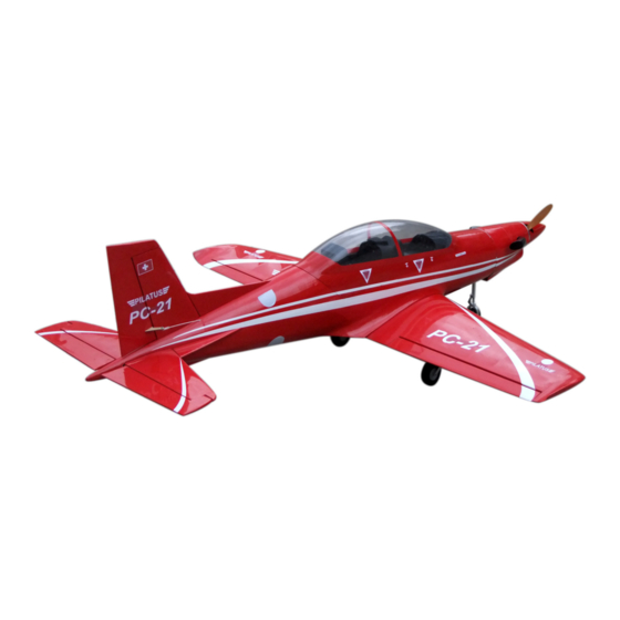
75
The side view once the model plane assemble completely.
73
Adjustment of the elevator,be sure it can work perfectly.
Top view
ELEVATOR
25mm
25mm
Position for
Side View
right diagram.
74
Centre of the Gravity.
96mm
14
PC - 21
Specification:
Length:
1624mm(64〞)
Wing span:
1397mm(55〞)
Wing area:
34.6sq.dm (3.72sq.ft)
Wing loading: 89.6g/sq.dm(29.4oz/sq.ft)
Flying weight: 3.1kg(6.8lbs)
Radio:
6ch & 6servos
Engine:
4-cycle 52-70
2-cycle 40-52
Motors:
4250 510KV
ESC:
60A
Battery:
6S 2200MAH 20C
Propeller:
14*7
SAFETY PRECAUTIONS
INSTRUCTION MANUAL
This R/C airplane is not a toy!
(The people under 18 years old is forbidden from flying this model)
First-time builders should seek advice from people having building
experience.If misused or abused,it can cause serious bodily injury
and damage to property.
Fly only in open areas and preferably at a dedicated R/C flying site.
We suggest having a qualified instructor carefully inspect your
airplane before its first flight.Please carefully read and follow all
instructions included with this airplane,your radio control system
and any other components purchased separately.
Advertisement
Table of Contents

Subscribe to Our Youtube Channel
Related Manuals for Pilatus PC - 21

Summary of Contents for Pilatus PC - 21
-
Page 1: Instruction Manual
Adjustment of the aileron and flap,be sure they can work Adjustment of the elevator,be sure it can work perfectly. perfectly. Side View AILERON PC - 21 25mm Top view 25mm ELEVATOR FLAP 30mm 25mm AILERON AILERON 25mm Position for Side View right diagram. - Page 2 Epoxy the fixed landing gear to the main wing. Install the nose landing gear servo. Set screw (3x4mm) (with 5 servos), Washer (2mm) Washer (2mm) Linkage Stopper 4 channel radio for aiplane is highly recommended for this model. Washer (2mm) Nut (2mm) Set screw (3x4mm) Li-Pox4 (2200mAh)
- Page 3 Assemble the aileron to main wing with instant type Accessory list for the coming installation steps. Trim the cowling along the shaded line. Mount the receiver and the battery in the fuselage. CA glue. Rod (2x300mm) TP Screw (2.3x12mm) Collar (2mm) Screw (2x10mm) Servo tray(70x58x2mm) Nut (2mm )
- Page 4 Apply instant type AB glue to the control horn and the slots in Cut off the surplus PVC part carefully along the shaded Fix the motor mount box to the fuselage with screws. Accessory list for the coming installation steps. the aileron, insert the control horn to the slots as illustration.
- Page 5 The consumers can also use motors for this plane.please find the Assemble the retract Mount the wings to the fuselage with screw . Install the servo of the throttle. assemble steps below.The front view when the motor install completion. Set screw (3x4mm) Washer (2mm) Washer (2mm) Linkage Stopper...
- Page 6 Apply instant type CA glue to the elevator and trim a Glue the elevator to the stabilizer by CA and epoxy. Drill four holes at the diameters as shown for engine mount. The sketch map when the engine install completion. slot in appropriate position in the elevator as illustration.
- Page 7 Lock the linkage to the control horn with screws and nuts Epoxy the fairing sheet to the slots in the fuselage as Accessory list for the coming installation steps. Assemble the steeling fullarm around the landing gear. as below. illustration. Blind Nut (4mm) Screw (4x35mm) Nut (2mm)
- Page 8 Apply instant type CA glue to aileron and pin hinge. Epoxy the control horns to the slots in the rudder. Assemble the rudder servo in the fuselage. Accessory list for the coming installation steps. Pin hinge(24x24mm) Collar (5mm) Screw (2x10mm) Nut (2mm ) Washer(2x6mm) Washer(3x6mm)
Need help?
Do you have a question about the PC - 21 and is the answer not in the manual?
Questions and answers