Table of Contents
Advertisement
Quick Links
INSTALLATION AND OPERATOR'S MANUAL
Balmar's Smartgauge™ battery monitoring system
provides accurate dependable information about
battery condition, without the need for shunts and
complicated programming. Simply select the battery
program that most closely matches your battery
technology.
The Smartgauge™ features Voltage and State of
Charge (SoC%) displays, and can be used to
provide alarms for low battery voltage and capacity.
As with all electrical components, take time to read
and follow the instructions provided in this manual.
Failure to do so could result in damage to the
Smartgauge™ and/or your electrical system.
SECTION
TOPIC
1.0
Introduction ....................................................................................................... ....... Page 2
2.0
Quick Start Guide ............................................................................................. ........ Page 3
2.1
Smartgauge Installation Basics ...................................................................... ........ Page 5
2.2
Important Installation Notes......................................................................... ............ Page 5
3.0
Initial Smartgauge Start Up ................................................................................ ..... Page 6
3.1
Determining Battery Charge Status......................................................................... Page 6
3.2
Calibrating Battery Charge Status................................................................... ........ Page 7
3.3
Power Up After Power Loss ......................................................................... ........... Page 7
4.0
Basic Monitor Use .............................................................................................. ...... Page 8
4.1
Set Up Menu............................................................................................................... Page 9
4.2
Set Up Mode - Battery Type ................................................................ .................... Page 9
4.3
Set Up Mode - Charge Status ............................................................ .................. Page 10
4.4
Alarm Functions .......................................................................... ........................... Page 10
4.5
Defeating Error Codes ................................................................. ......................... Page 13
4.6
Set Up Display Behavior......................................................... ................................ Page 14
4.7
Set Up Display Brightness ............................................................... ..................... Page 14
4.8
Set Up Menu Lock ........................................................................... ....................... Page 15
5.0
Error Codes.............................................................................................................. Page 15
6.0
Reset to Factory Defaults ............................................................. ......................... Page 16
7.0
Alarm Outputs .............................................................................. .......................... Page 17
8.0
Alarm Notes ........................................................................ .................................... Page 17
9.0
Addendum................................................................................................................ Page 17
10.0
Specifications .................................................................................... ..................... Page 18
11.0
Warranty ........................................................................................ .......................... Page 19
12.0
Smartgauge Display Flowcharts................................................ ............................ Page 19
BALMAR LLC. MARYSVILLE, WA 98271 USA - WWW.BALMAR.NET - +1-360-435-6100
©2016 Balmar LLC. Reproduction is forbidden without permission
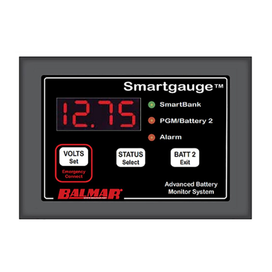
VOLTS
Set
Emergency
Connect
CONTENTS
Smartgauge
BATTERY MONITOR
Smartgauge
SmartBank
SmartBank
PGM/Battery 2
Alarm
STATUS
BATT 2
Select
Exit
Advanced Battery
Monitor System
QF-137 Rev B
™
™
PAGE
Advertisement
Table of Contents

Summary of Contents for Balmar Smartgauge
-
Page 1: Table Of Contents
10.0 Specifications ......................Page 18 11.0 Warranty ........................Page 19 12.0 Smartgauge Display Flowcharts................Page 19 BALMAR LLC. MARYSVILLE, WA 98271 USA – WWW.BALMAR.NET – +1-360-435-6100 QF-137 Rev B ©2016 Balmar LLC. Reproduction is forbidden without permission... -
Page 2: Introduction
Smartgauge™ compares real world data with those models to generate information on the battery’s State of Charge. In independent testing Smartgauge™ was found to be within 5% accuracy at all times. Highly accurate SoC information not only allows you to confidently make decisions about how you use your electrical system, it also allows you to automate certain functions –... -
Page 3: Quick Start Guide
Smartgauge™ is in compliance with the requirements of EU Electromagnetic Compatibility (EMC) Directive 89/336/EEC. Smartgauge™ complies with RoHS (Reduction of Hazardous Substances) Directive 2002/95/EC. Smartgauge™ contains no Lead. At the end of life, Smartgauge™ should be disposed of as normal electrical waste. - Page 4 Once the ground and positive sense wires are connected, the monitor display will indicate the software and battery model revisions. The Smartgauge™ will then show “bt 1” in the display and the PGM/Batt 2 LED will be flashing. Use the STATUS button to scroll through the program choices, as listed below:...
-
Page 5: Smartgauge Installation Basics
(primary) battery bank. The B2 terminal should be connected to the engine starting battery via the secondary sense wire. 2. Both battery banks must be either 12 volts or 24 volts. The Smartgauge ™ cannot be used in a mixed instal- lation with 12-volt and 24-volt battery banks. -
Page 6: Initial Smartgauge Start Up
(House Battery Bank) Volts Status (State of Charge) On powering up Smartgauge™ for the first time, the display will show the software revision information. The fol- lowing are just examples. They are required for troubleshooting. r1.03 = Software revision 1.03 b1.05 = Battery model revision 1.05... -
Page 7: Calibrating Battery Charge Status
If either of these happen, then Smartgauge™ simply will not operate. Once normal battery voltage is restored, the Smartgauge™ will show a permanent HI or LO reading and an “E04” error. If this happens the solution is to reset the monitor to factory default value, ensure the battery voltage is correct, and re-apply power. -
Page 8: Basic Monitor Use
SECTION 3.3 – POWER UP FOLLOWING POWER LOSS PAGE 8 There is no need to reset any other functions. Smartgauge™ will remember all settings (with the exception that status alarms will have been disabled). Refer to the flow chart headed “Re power up following power failure” for details of the expected display at the back of the manual. -
Page 9: Set Up Menu
2. The other type of AGM have additional chemicals in the battery and require lower charge voltages and the off load terminal voltages will be similar to gel cells. This type require Smartgauge to be set to battery type 3. -
Page 10: Set Up Mode - Charge Status
SECTION 4.4 – SET UP MODE – ALARM FUNCTIONS There are two levels of alarm settings in Smartgauge ™ . The first is the Primary Alarm which can be set OFF or can be used to access low/high voltage or low SoC function. See Section 7.0 for information regarding alarm outputs. - Page 11 Pressing the Select button will scroll this value up to 16.50 volts, it will then wrap round to whatever value was previously entered for the alarm activation voltage. This means that no matter what you do, Smartgauge™ will not allow this value to be set lower than the activation voltage.
- Page 12 The timed period and the display will be accurate to within about 10% Also note that internally Smartgauge™ counts in seconds whereas the display only shows the minutes. It is rounded to the nearest min- ute so when the display counts down and reaches zero, there could in fact be 30 seconds remaining.
-
Page 13: Defeating Error Codes
SECTION 4.5 – SET UP MODE – DEFEATING ERROR CODES In some circumstances, it may be necessary to defeat the error code functions in Smartgauge™. Most installations, particularly those where loads are used at the same time as charging, use what are known as 2 or 3 stage chargers. -
Page 14: Set Up Display Behavior
SECTION 4.7 – SET UP MODE – DISPLAY BRIGHTNESS The display brightness is fully adjustable to enable the Smartgauge™ to be used in any light conditions. One of the advantages of this type of display (LED – Light Emitting Diode) as opposed to the other common display (LCD –... -
Page 15: Set Up Menu Lock
SECTION 5.0 – ERROR CODES Error codes do not indicate a problem with Smartgauge™. They indicate a problem with the installation or other equipment such as chargers. For instance, a continual “E03” error signifies a charger fault, not a Smartgauge™ fault. -
Page 16: Reset To Factory Defaults
SmartGauge™ can accurately measure voltages between 9.00 and 17.00 volts in 12 volt mode and between 18.00 and 34.00 volts in 24 volt mode. If these limits are exceeded SmartGauge™ has no way of measuring the actual voltage. Also, if these limits are exceeded there is something seriously wrong with the installation. -
Page 17: Alarm Outputs
Smartgauge™ automatically adjusts itself to compensate for battery aging and the consequent reduced battery capacity as they get older. This is also one of the ways in which Smartgauge™ is superior to a meter based on the amp hours counting principle. This is a continual process that continues throughout the life of the batteries so that Smartgauge™... -
Page 18: Specifications
Smartgauge™ will provide a dependable indication (certainly better than an amp hours counter – and certainly better than a volt meter but it could be that Smartgauge™ shows the charge status to have reached (as a worst case example) 100% when in actual fact the batteries have only reached 90%. -
Page 19: Warranty
PAGE 19 SECTION 11.0 – WARRANTY Smartgauge™ is warranted to be free of workmanship defects for a period of 2 years. In the event of a warranty claim, please contact Balmar Customer Service at +1-360-435-6100 for a return authorization. Exclusions to this warranty include: 1. - Page 20 SECTION 12.0 – SMARTGAUGE FLOW CHARTS PAGE 20 12.3 – Set Up Menu VOLTS BUTTO N NORMAL 12.65 C 76 OPERATIO N STATUS BUTTO N BATT 2 BUTTO N bt x C X X PA 0 PA U PA S...
Need help?
Do you have a question about the Smartgauge and is the answer not in the manual?
Questions and answers