Table of Contents
Advertisement
Advertisement
Table of Contents

Summary of Contents for D'Alessandro Termomeccanica CS Small 20
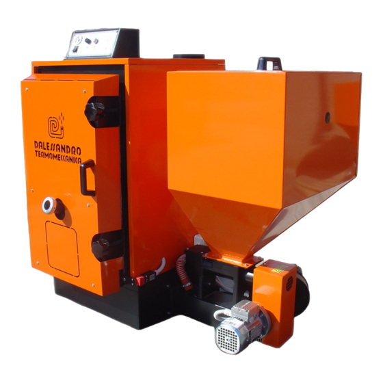
- Page 1 C.da Cerreto, 55 - 66010 MIGLIANICO (CH) – Italy Tel. (+39) 0871/950329 Fax (+39) 0871/950687 http://www.caldaiedalessandro.it e-mail: info@caldaiedalessandro.it Wood biomass heat generator Series CS SMALL Models from 20 to 100 USE AND MAINTENANCE GUIDE Ver. 1.0 - QCSSMALLXIT0114...
- Page 2 Flue The flue represents one of the fundamental elements of the heat generator. The correct designing of the fumes evacuation system guarantees the correct and always efficient generator functioning and prevents the potentially dangerous situations for the user. For a correct installation, refer to section 6.5 pag.17 of this manual and, however, use experienced staff.
- Page 3 Electrical connections The generator is equipped with a main switch not automatic ISOLATOR type. It is recommended to protect the power supply line using a differential magne- tothermic switch. Refer to the attached control board manual for electrical connections.
-
Page 4: Table Of Contents
CONTENTS GENERAL INFORMATION Identification and purpose of the document Technical data plate CE Marking Reference standards Typographic Conventions Guarantee and Responsability SAFETY AND RESIDUAL RISKS Risks connected to the use of the machine Residual risks Intended use of generator Improper use of generator FUNCTIONING, TECHNICAL FEATURES AND DIMENSIONS Generator operation illustration Generator operation description... - Page 5 Frequent heat request condition Carburation Comburent air regulation Fuel regulation Switch off CLEANING General information MAINTENANCE General information ANOMALIES, FAILURES AND MALFUNCTIONS, questions and an- swers 10.1 Table of anomalies and failures 10.2 Table of malfunctions NOISE 11.1 General information 11.2 Sound emission value DECOMMISSIONING AND SCRAPPING 12.1 General information...
-
Page 6: General Information
1. GENERAL INFORMATION 1.1 Identification and purpose of the document This instruction guide drafted by D’ALESSANDRO TERMOMECCANICA is an integral part of the heat generator. Any reproduction, even partial, is prohibited. The aim of this manual is to provide all the necessary information for a correct use guaranteeing maximum safety for people, animals and objects. -
Page 7: Reference Standards
1.4 Reference standards This manual has been written in compliance with the following Directives, Laws and Standards: 1. Directive 85/374/CEE on responsability for defective products 2. Directive 92/59/ CEE on General Safety of products 3. Directive 2006/42/CE on Machinery safety 4. -
Page 8: Safety And Residual Risks
2. SAFETY AND RESIDUAL RISKS 2.1 Risks connected to the use of the machine The generator is built in compliance with the main safety requirements laid down in the European Directives. The European and National Standards concerning the safety of this type of machine have been considered during the design stage, taking the state of the art into account. -
Page 9: Intended Use Of Generator
PROTECTIVE HELMET IS MANDATORY During every generator tran sport or handling operation PROTECTIVE MASK IS MANDATORY During maintenance and cleaning operation on the flues. 2.3 Intended use of the generator The generator produces low pressure hot water and is suitable for non-pulverised solid fuel combustion with mechanised feeding. -
Page 10: Functioning, Technical Features And Dimensions
3. FUNCTIONING, TECHNICAL FEATURES AND DIMENSIONS 3.1 Generator operation illustration The generator is a three flue passes type for the production of hot water for residential and indu- strial heating. 3.2 Generator operation description The fuel descends by gravity from the hopper into the upper feeding screw, where it is pusher into the star valve (optional) falling then into the burner feeding screw. -
Page 11: Technical Features
3.3 Technical features Tables 3.3.1 and tab.3.3.2 show in detail the CS Small technical data. For further information please contact the D’ALESSANDRO TERMOMECCANICA technical office. CS Small CS Small CS Small CS Small CS Small CS Small MODELLI CALDAIE / MODELS BOILERS potenza nominale (kW) nominal output... -
Page 12: List Of Components And Spare Parts
3.4 List of components and spare parts The main CS Small generator components are shown in the figures below: fig. 3.4.1 fig. 3.4.2 DESCRIPTION The list of parts will be subsequently mentioned for iden- tifying spare parts and as a reference for descriptions in Control panel the following chapters. -
Page 13: General Dimensions
3.5 General dimensions MODELLI / MODELS CS Small 20 CS Small 30 CS Small 45 CS Small 60 CS Small 80 CS Small 100 DIMENSIONI / DIMENSION (mm) (mm) 1330 1355 (mm) 1025 (mm) 1200 (mm) 1000 1100 1200 1400... -
Page 14: Fuels
4. FUELS 4.1 Fuels used Crushed solid fuel based on wood can be used, such as: · Wooden pellets · Crushed almond, walnut and hazel nut shells · Exhaust olive residues · Crushed olive stones · Crushed peach, apricot and other similar stones The nominal power of generators is guaranteed with a biomass fuel humidity not over 10-15%. - Page 15 Lifting hook supplied by D’Alessandro Termomeccanica models 20-30-40 models 60-80-100...
-
Page 16: Installation And Testing
6. INSTALLATION AND TESTING 6.1 General installation requirements The electrical and thermo-hydraulic installation of the heat generator and any other assistance or maintenance operation must be carried out by personnel registered in the professional register established at the Chamber of Commerce, in compliance with Ministerial Decree 37/08. The thermo-hydraulicand electrical installers must release a Cartification of Conformity in com- pliance with Ministerial Decree 37/08 and implementation regulation. -
Page 17: Flue And Draught
6.5 Flue and draught The flue is one of the most important elements for a correct generator operation. In general a good draught is obtained when flue is thermally insulated, designed with a double wall and insulated to prevent the fumes from cooling, thus maintaining the pressure difference that allows the fumes to go up the flue to the external outlet. -
Page 18: Electrical System And Connections
fig. 6.5.3 6.6 Electric plan and connections The generator is equipped with a non-automatic main switch. We recommend protecting the power supply line of the plant by means of a differential magneto-thermal switch with intervention threshold not higher than 30 mA All foreign masses and piping will be connected by means of equipotential pipe to a ground node. -
Page 19: Power On, Start-Up And Checking
The fuel has to reach the base of the ignition plug. Fig 7.1 : CS SMALL 20-40 burner NOTE: CS SMALL 60-100 burner has different dimensions and shape than fig. 7.1 but the main principle is the same. The burner has to be filled with fuel up to the base of the ignition plug. -
Page 20: Normal Operation
7.3 Regime functioning After start-up and regulations, the heat generator functioning proceeds automatically. 7.4 Frequent heat request condition During regime functioning the fuel conveying screw and the comburent air are regulated by a regulation thermostat: The screw and electric fans stop once the pre-fixed maximum temperature is reached ... -
Page 21: Fuel Regulation
8 of standard EN303-5 for the fuel of test “C”, approximate dimensions Ø6 x 25mm and an apparent mass density between 600 and 660 kg/mc. FUEL REGULATION min Hz max Hz mod.CS SMALL 20 mod.CS SMALL 30 mod.CS SMALL 40 fig. 7.4 mod.CS SMALL 60 mod.CS SMALL 80... -
Page 22: Cleaning
8. CLEANING 8.1 General The firebox and the flues must be periodically cleaned from combustion solid residues (ashes). Keeping the flues free from ashes ensures an effective draught and the best geerator efficiency. Table 8.1 lists the cleaning operations to be carried out in the chronological order. CAUTION !! BEFORE CLEANING, DISCONNECT THE ELECTRIC ENERGY FROM THE GENE- RATOR BY INTERVENING ON THE MAIN SWITCH AND ENSURE THAT THE RESI-... - Page 23 FUEL HOPPER OPERATION: checking and cleaning of the empty hopper from dust and incrustation due to hu- midity and to the type of the used fuel. PERIODICITY: 30 / 60 days NOTES: check the fuel does not contain foreign bodies that could damage the screws. REFERENCE: fig.3.4.1 pos.12 tab.
-
Page 24: Maintenance
9. MAINTENANCE 9.1 General The heat generator must be submitted to regular maintenance to guarantee the efficiency of all the components determining the correct operating of the generator and its main yield. Tab.9.1 summarises the main operations. ATTENTION!! MAINTENANCE MUST BE CARRIED OUT ONLY BY QUALIFIED STAFF ATTENTION !! BEFORE PERFORMING MAINTENANCE OPERATIONS , DISCONNECT THE POW- ER SUPPLY FROM THE GENERATOR BY INTERVENING ON THE MAIN SWITCH... -
Page 25: Table Of Anomalies And Failures
10. ANOMALIES, FAULTS AND MALFUNCTIONING - FAQ AND ANSWERS 10.1 Anomalies and faults table. FAQ and answers ATTENTION!! BEFORE PERFORMING THE OPERATIONS DESCRIBED IN CHAP. 10, DISCON- NECT THE ELECTRIC ENERGY FROM THE GENERATOR BY INTERVENING ON THE MAIN SWITCH AND ENSURE THAT THE RESIDUE FUEL INSIDE THE FIRE- BOX IS OFF AND HAS COOLED DOWN SIGN PROBABLE CAUSES... -
Page 26: General Information
fig. 10.1 10.2 Table of mulfunctions. Questions and answers PROBLEM POSSIBLE CAUSE SOLUTION a) make sure that the flue draught is that re- a) If not, refer to qualified personnel quired in table 3.3.1 Smoke returns inside the fuel hopper a) check the balance between fuel flow rate a) Should the problem persist, call for technical assistance... - Page 27 NOTES...
-
Page 28: Ccopy Of Declaration Of Conformity
C. COPY OF DECLARATION OF CONFORMITY DECLARATION OF CONFORMITY D'Alessandro Termomeccanica C.da Cerreto, 55 - 66010 MIGLIANICO (CH) DECLARES Under his owjn exclusive responsabilità that SOLID FUEL BOILERS With AUTOMATIC FEEDING Series CS Small Models 20-30-45-60-80-100 Serial number XXXXX To which this declaration refers to COMPLY WITH Directive 2006/42/CE (Machine Directive), Directive 2006/92/CE (Electrical material safety), Direc- tive 2004/108/CEE (Electromagnetic compatibility) integrated by CE marking. -
Page 29: Dcopy Of Partial Switching Off Declaration
D. COPY OF PARTIAL SWITCHING OFF DECLARATION CS Small...
Need help?
Do you have a question about the CS Small 20 and is the answer not in the manual?
Questions and answers