
Subscribe to Our Youtube Channel
Related Manuals for HobbyKing AssaultReaper 500

Summary of Contents for HobbyKing AssaultReaper 500
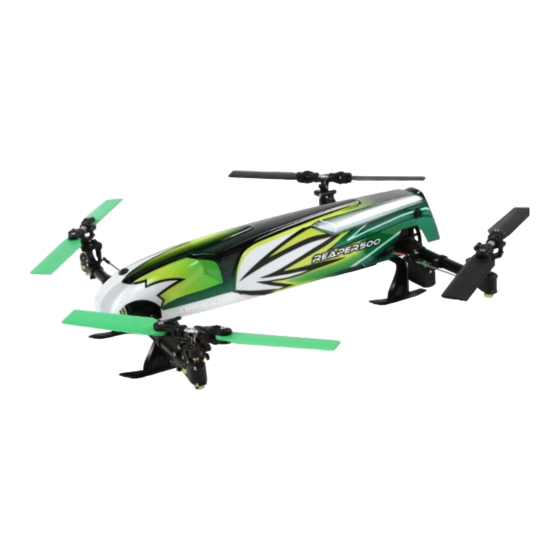
- Page 1 Specification: TYPE: Collective Pitch Electric 3D Quadcopter Rotor Diameter: 118MM Length:635 MM Width: 365 MM Weight: 986g w/out battery Flying weight : 1240g w/battery...
-
Page 2: Table Of Contents
3.0 Assault Reaper 500 3D Assembly 3-13 when operating this product. HobbyKing / the seller assumes no liability for the operation or use of this product. 4.0 Main Controller Set Up Guidelines This product is intended for use by experienced pilots aged 14 years or more. -
Page 3: Assault Reaper 500 3D Set Up Instructions
2.0 Assault Reaper 500 3D Set Up Instructions Rotor4 (Counter-Clockwise) Rotor1 (Clockwise) Front Leading Edge Leading Edge of the blade of the blade Servo 4 Servo 1 Leading Edge Leading Edge of the blade Rotor2 (Counter-Clockwise) of the blade Rotor3 (Clockwise) Servo 3 Servo 2 Back... -
Page 4: Assault Reaper 500 3D Assembly
3.0 Assault Reaper 500 3D Assembly No.1 Front Pulley Block Assembly (1) Slide the drive belt through the left and right fixed tubes respectively. Right fixed tube (2) Face the fixed tube gap downwards, secure to the front pulley block, Drvien belt and tighten the fixing screw. - Page 5 No.2 Back Pulley Block Assembly (1) Slide the drive belt through the left and right fixed tubes respectively. (2) Face the fixed tube gap downwards, secure to the back pulley block, and tighten the fixing screw. Right fixed tube Back pulley block M2x8 screw Drvien belt M2x8 screw...
- Page 6 NO.3 Front End Assembly Drive Shaft And Middle Fixed Tube Driven wheel (1) Place the front end of the drive shaft through the drive wheel and bearing, tighten the fixing screw on the flat position. Flat position (2) Fit the middle fixed tube to the front pulley block, and tighten the fixing screw.
- Page 7 NO.4 Rear End Assembly Drive Shaft and Middle Fixed Tube. Middel fixed tube M2x8 screw Driven shaft M2 fixing nut Driven wheel M3x3 screw (1) Slide the back end of the drive shaft through the Second flat position drive wheel and bearing, tighten the fixing screw on the second flat position.
- Page 8 NO.5 Main Drive Gear and Brushless Motor Assembly. (1) Fit the main drive gear onto the drive shaft, and tighten the fixing screw on the flat position. (2) Fit the brushless motor to the back pulley block, move it up and down until the main drive gear and motor mesh smoothly, then tighten the fixing screw to secure.
- Page 9 NO.6 Instructions For Drive Belt Assembly (1) The arrows represent the rotation direction. (2) When assembling the drive belt try to keep it tight to avoid vibration in operation. Front Rotate the end of the drive belt 90 degrees Rotate the end of the drive belt 90 degrees counter-clockwise when assembled.
- Page 10 NO.7 Rotor 2 / Rotor 4 Assembly M2x14 screw (1) Install the drive belt to Rotor 2, ensure the rotation is correct. Control the swing arm (2) Install Rotor 2 front and rear seat, and tighten the fixing screw. (3) Install Rotor 4 in the same manner as Rotor 2. Back fixed seat Rotor2 Driven belt...
- Page 11 NO.8 Rotor 1 / Rotor 3 Assembly M2x14 (1) Install the drive belt to Rotor 3, ensure the rotation is correct. (2) Install the Rotor 3 front and rear fixed seat, and tighten the fixing screw. Control the swing arm (3) Install Rotor 1 in the same manner as Rotor 3.
- Page 12 No.9 Pull Rod Assembly Pull rod Pull rod Once the steering servos have been positioned to centre, the steering gear control swing arm must be positioned at an angle of 90 degrees to ensure correct Pull rod operation. (2) Connect the pull rod joint buckle to the ball end, the propeller PITC should be at an angle of 0 degrees.
- Page 13 No.10 Reinforcing Plate, Skid Landing and Propeller Assembly. Front M3x14 screw M3 fixing nut Leading Edge Leading Edge of the blade of the blade Reinforcing plate (1) Install the reinforcing plate to the bottom of the front back pulley block. KB2x5 (2) Install the bottom cover and skid landing to the bottom of the front, back pulley block.
- Page 14 No.11 ESC, Main Controller, Receiver, Battery, Front Canopy Assembly Canopy Canopy support beam (1) Install the ESC to the backend of the mount plate. (2) Install the main controller to the mount plate. (3) Install the receiver to the mount plate. (4) Install the battery to the mount plate.
-
Page 15: Main Controller Set Up Guidelines
4.0 Main Controller Set Up Guidelines AUX1 IN: connect to receiver AUX1 port Servo 1: connect to servo 1 Servo 2: connect to servo 2 Servo 3: connect to servo 3 Servo 4: connect to servo 4 THRO OUT: connect to ESC RUDD IN: connect to receiver RUDD port THRO IN: connect to receiver THRO port AILE IN: connect to receiver AILE port... - Page 16 5.0 Brushless Speed Controller Set up Connect to main controller THRO OUT port —— Black Yellow —— Blue Green Brushless Motor —— Connect to battery Attention: The brushless motor should rotate in a clockwise direction, if not, exchange any two the motor connection wires to obtain the correct rotation.
- Page 17 6.0 T-SIX Transmitter Settings 6.1 Initial INFO Screen Elevator Trim(Mode 1) Throttle Trim(Mode 1) Throttle Trim(Mode 2) Elevator Trim(Mode 2) 7.2V Voltage REAPER50 Model Type DN 06:00 Time MDL 1 Current model number [ NORM ] Helicopter Flight Mode Current Model HELI Rudder Trim Aileron Trim...
- Page 18 (1) Voltage: When the transmitter voltage drops below 4.3 volts, (4) Trim set up: The trim set up function allows servo movement “Warning Low Battery” will flash along with an alarm sound. If you adjustment. are flying when this occurs, land immediately. (5) Model display: you can see the selected model directly after your (2) Timer: Timer function allows you to program a Count Down timer or model type has been selected.
- Page 19 (1) LIST Key: when this key is pressed the screen changes to the Function Listing screen. (2) ENTER Key: If this key is pressed when the INFO screen is being displayed, the screen will change to the My list screen. This can be used for moving to each of the other functions.
- Page 20 6.5 MODEL TYPE MODEL TYPE Rotate Press ROLLER ROLLER SETUP LIST MODEL TYPE ACRO HELI Rotate ROLLER to choose HELI, press ROLLER to confirm. When finished, press ROLLER to return to SETUP LIST menu. 6.6 SWASH TYPE SWASH TYPE Rotate Press ROLLER ROLLER...
- Page 21 6.8 GYRO GYRO Rotate Press ROLLER ROLLER FUNCTION LIST GYRO RATE SW-GYRO POS0: 80.0% POS1: 70.0% POS1: 50.0% Rotate ROLLER to choose and change the settings and press ROLLER to confirm. When finished, press ROLLER to return to FUNCTION LIST menu.
- Page 22 6.10 PITC CUR PITC CUR PITC CUR Rotate Press STU HOLD NORM NORM STU HOLD ROLLER ROLLER FUNCTION LIST PITC CUR L 40.0 25.0 L 40.0 25.0 2 50.0 38.0 25.0 2 50.0 38.0 25.0 3 58.0 50.0 50.0 3 58.0 50.0 50.0 4 68.0...
-
Page 23: Binding The Transmitter And Receiver
7.0 Binding the Transmitter and Receiver binding plug (1) Insert the bind plug in the BATT/ BIND slot on the receiver. (2) Move the throttle sticker to the LOW/OFF position. Then power on the radio. (3) Connect the flight battery to the receiver, the LED will flash quickly. (4) When the LED becomes a solid continuous light binding is complete. - Page 24 8.0 Normal flight Aircraft( is the nose direction) Mode 1 Mode 2 Up / down Forward / backward Left-leaning / right-leaning Head direction is horizontal level...
- Page 25 9.0 Acrobatic flight Aircraft( is the nose direction) Mode 1 Mode 2 Up / down Forward / backward Left-leaning / right-leaning Head direction is horizontal level...
Need help?
Do you have a question about the AssaultReaper 500 and is the answer not in the manual?
Questions and answers