Control Techniques Unidrive M300 Quick Start Manual
Enhance throughput with
machine safety
Hide thumbs
Also See for Unidrive M300:
- Step-by-step manual (42 pages) ,
- Step-by-step manual (52 pages) ,
- Quick start manual (4 pages)

Subscribe to Our Youtube Channel
Related Manuals for Control Techniques Unidrive M300


Summary of Contents for Control Techniques Unidrive M300
- Page 1 Quick Start Guide Unidrive M300/ HS30 Frame sizes 1 to 4 Enhance throughput with Machine Safety Part Number: 0478-0039-07 Issue: 7...
- Page 2 Original Instructions For the purposes of compliance with the EU Machinery Directive 2006/42/EC This guide is intended to provide basic information required in order to set-up a drive to run a motor. For more detailed installation information, please refer to the relevant drive documentation which is available to download from: www.drive-setup.com Warnings, Cautions and Notes...
-
Page 3: Table Of Contents
Saving parameters ....................25 Restoring parameter defaults ................25 Basic parameters (Menu 0) ...............26 Menu 0: Basic parameters ..................26 Unidrive M300/HS30 parameter descriptions ............32 Running the motor ..................55 Diagnostics ....................56 Alarm indications ....................60 NV Media Card Operation .................61 Machine Control Studio ................62... - Page 4 EN 61000-3-2:2014 Applicable where input current < 16 A. No limits apply for professional equipment where input power ≥1 kW. These products comply with the Restriction of Hazardous Substances Directive (2011/65/EU), the Low Voltage Directive (2014/35/EU) and the Electromagnetic Compatibility Directive (2014/30/EU). Unidrive M300/HS30 Quick Start Guide Issue Number: 7...
- Page 5 EMC. Refer to the Product Documentation. An EMC data sheet is available giving detailed information. The assembler is responsible for ensuring that the end product or system complies with all the relevant laws in the country where it is to be used. Unidrive M300/HS30 Quick Start Guide Issue Number: 7...
- Page 6 TUV Rheinland Industrie Service GmbH Am Grauen Stein D-51105 Köln Germany Notified body identification number: 0035 The harmonized standards used are shown below: EC type-examination certificate numbers: 01/205/5270.01/14 dated 2014-11-11 01/205/5387.01/15 dated 2015-01-29 01/205/5383.02/15 dated 2015-04-21 Unidrive M300/HS30 Quick Start Guide Issue Number: 7...
- Page 7 EMC. Refer to the Product Documentation. An EMC data sheet is available giving detailed information. The assembler is responsible for ensuring that the end product or system complies with all the relevant laws in the country where it is to be used. Unidrive M300/HS30 Quick Start Guide Issue Number: 7...
-
Page 8: Product Information
04400135 16.3 13.5 04400170 20.7 The nominal cable sizes shown in the table above, are provided as a guide only. Ensure NOTE that the cables used conform to the local wiring regulations. Unidrive M300/HS30 Quick Start Guide Issue Number: 7... -
Page 9: Options
Name Further details Purple SI-PROFIBUS Medium SI-DeviceNet Grey Light Grey SI-CANopen Fieldbus Beige SI-Ethernet See relevant option module User Guide Brown Red SI-EtherCAT Yellow SI-PROFINET V2 Green Automation Orange SI-I/O (I/O expansion) Unidrive M300/HS30 Quick Start Guide Issue Number: 7... -
Page 10: Mechanical Installation
A minimum clearance of 100 mm (3.94 in) above and below Frame 01 to 04 products is NOTE required for applications where the product is subjected to rated load and rated ambient temperature. Unidrive M300/HS30 Quick Start Guide Issue Number: 7... - Page 11 Drive size Tightening torque 1 to 3 1.3 N m (1 lb ft) to 1.6 N m (1.2 lb ft) 2.5 N m (1.8 lb ft) to 2.8 N m (2.1 lb ft) Unidrive M300/HS30 Quick Start Guide Issue Number: 7...
- Page 12 8. DC bus + 9. DC bus - 10. Motor connections 11. AC supply connections 12. Ground connections 13. Safe Torque Off connections on page 22 Before removing the screw, refer to section 4.5 EMC Unidrive M300/HS30 Quick Start Guide Issue Number: 7...
-
Page 13: Electrical Installation
Table 4-1 Braking resistor resistance and power rating (100 V) Minimum Instantaneous Continuous Model resistance* power rating power rating Ω 01100017 0.25 01100024 0.37 02100042 0.75 02100056 * Resistor tolerance: ±10 % Unidrive M300/HS30 Quick Start Guide Issue Number: 7... - Page 14 Table 4-3 Braking resistor resistance and power rating (400 V) Minimum Instantaneous Continuous Model resistance* power rating power rating Ω 02400013 0.37 02400018 0.55 02400023 0.75 02400032 02400041 03400056 03400073 03400094 04400135 11.2 04400170 * Resistor tolerance: ±10 % Unidrive M300/HS30 Quick Start Guide Issue Number: 7...
-
Page 15: Ground Leakage
The drive is provided with two ground connections to facilitate this. Both ground connections are necessary to meet EN 61800- WARNING 5-1: 2007. Unidrive M300/HS30 Quick Start Guide Issue Number: 7... -
Page 16: Control Terminal Configurations And Wiring
Action will only occur if the drive is inactive and no User Actions are running. Otherwise, the parameter will return to its pre altered value on exit from edit mode. All parameters are saved if this parameter changes. Unidrive M300/HS30 Quick Start Guide Issue Number: 7... - Page 17 + 10 V output Voltage speed reference input (AI 2) Analog output 1 (motor frequency) + 24 V output Digital output (zero frequency) Unassigned Run forward Run reverse Analog input 1/ input 2 select Unidrive M300/HS30 Quick Start Guide Issue Number: 7...
- Page 18 Unassigned Terminal 5 Terminal 14 Reference selected Run forward Analog reference 1* Preset speed 2* Run reverse Preset speed 3* Preset speed 4* Reference select * Refer to the Control User Guide. Unidrive M300/HS30 Quick Start Guide Issue Number: 7...
- Page 19 (AI 2) Analog output 1 (motor frequency) + 24 V output Digital output (zero frequency) Unassigned Run forward Run reverse Analog input 1/ input 2 select Unidrive M300/HS30 Quick Start Guide Issue Number: 7...
- Page 20 (zero frequency) 4 = zero at power-up and drive disabled, Unassigned only change when drive is running. Run forward Run reverse 14 UP * Refer to the Control User Guide. Unidrive M300/HS30 Quick Start Guide Issue Number: 7...
- Page 21 Pid reference • PID output lower limit (%) reference input input (AI 2) Analog output 1 (motor frequency) + 24 V output Digital output (zero frequency) Unassigned Run forward Run reverse Pid enable Unidrive M300/HS30 Quick Start Guide Issue Number: 7...
-
Page 22: Emc
Equipment which is sensitive to electrical interference operating nearby In this case it is necessary to use: • The optional external EMC filter • A shielded motor cable, with shield clamped to the grounded metal panel Unidrive M300/HS30 Quick Start Guide Issue Number: 7... -
Page 23: Safe Torque Off (Sto)
A shielded control cable, with shield clamped to the grounded metal panel Full instructions are given in the Power Installation Guide. A full range of external EMC filters are also available for use with Unidrive M300/HS30, shown in the Power Installation Guide. -
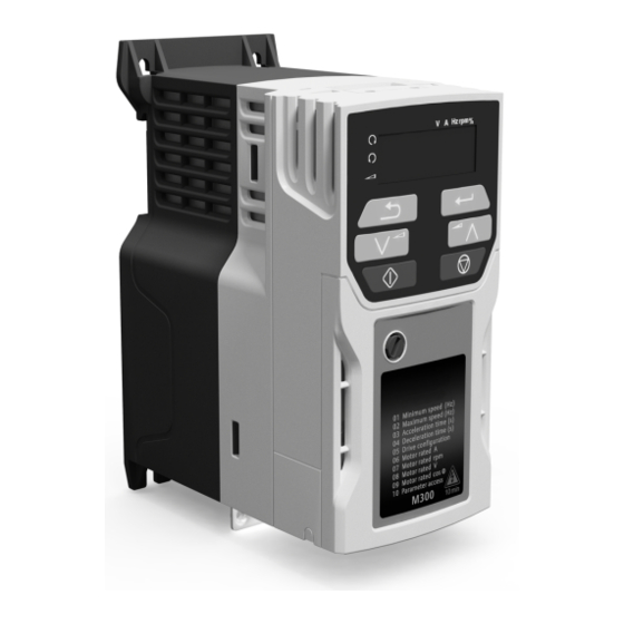
Page 24: Keypad And Display
Figure 5-1 Unidrive M300/HS30 keypad detail (1) The Enter button is used to enter parameter view or edit mode, or to accept a parameter edit. -
Page 25: Saving Parameters
1244 (60 Hz settings) in Pr 00 or Pr mm.000). 3. Either: • Press the red reset button • Carry out a drive reset through serial communications by setting Pr 10.038 to 100 Unidrive M300/HS30 Quick Start Guide Issue Number: 7... -
Page 26: Basic Parameters (Menu 0)
Status Mode 0.000 to 30.999 2.001 RW Num PT US Parameter 1 Customer Defined 0.000 to 10.000 1.000 RW Num Scaling User Security Code 0 to 9999 RW Num ND PT US Unidrive M300/HS30 Quick Start Guide Issue Number: 7... - Page 27 0.00 to 20.00 Hz 1.00 Hz RW Num Frequency Brake Controller Brake Apply 0.00 to 20.00 Hz 2.00 Hz RW Num Frequency Brake Controller 0.0 to 25.0 s 1.0 s RW Num Brake Delay Unidrive M300/HS30 Quick Start Guide Issue Number: 7...
- Page 28 ± Drive Maximum Current A Current Digital I/O Read 0 to 2047 ND NC PT Word Reference On Off (0) or On (1) ND NC PT Reverse Select Off (0) or On (1) ND NC PT Unidrive M300/HS30 Quick Start Guide Issue Number: 7...
- Page 29 ***** With the Unidrive HS30, the maximum is 180,000.0 rpm. Read / Read Number Binary Text string Filtered Write only parameter parameter parameter Protected Rating Power-down default User save DE Destination copied parameter dependent save value Unidrive M300/HS30 Quick Start Guide Issue Number: 7...
- Page 30 Reference Selected Menu 0 only Input Read-write (RW) Read-write (RW) 00.XXX terminals parameter parameter Read-only (RO) Read-only (RO) Output 00.XXX parameter parameter terminals The parameters are all shown in their default settings Unidrive M300/HS30 Quick Start Guide Issue Number: 7...
- Page 31 Ramp Mode Low Frequency Select Motor Voltage Boost Dynamic V/f Select Motor Rpm Output Frequency Power stage Output Voltage Maximum Switching Frequency Motor Rpm Current Torque Magnitude Producing Current Magnetising Current Resistor optional Unidrive M300/HS30 Quick Start Guide Issue Number: 7...
-
Page 32: Unidrive M300/Hs30 Parameter Descriptions
0.0 to 32000.0 s/100 Hz 10.0 s/100 Hz RFC-A Set Pr 04 at the required rate of deceleration. Note that larger values produce lower deceleration. The rate applies in both directions of rotation. Unidrive M300/HS30 Quick Start Guide Issue Number: 7... - Page 33 The motor rated current is used in the following: • Current limits • Motor thermal overload protection • Vector mode voltage control • Slip compensation • Dynamic V/F control Unidrive M300/HS30 Quick Start Guide Issue Number: 7...
- Page 34 The drive can measure the motor rated power factor by performing a rotating autotune (see Autotune (Pr 38). User Security Status LEVEL.1 (0), LEVEL.2 (1), LEVEL.1 (0) ALL (2), StAtUS (3), no.Acc (4) RFC-A Unidrive M300/HS30 Quick Start Guide Issue Number: 7...
- Page 35 Action will only occur if the drive is inactive. If the drive is active, the parameter will return to its pre- altered value on exit from edit mode. Jog Reference 0.00 to 300.00 Hz 1.50 Hz RFC-A Defines the reference when jog is enabled. Unidrive M300/HS30 Quick Start Guide Issue Number: 7...
- Page 36 Bipolar Reference Enable Off (0) or On (1) Off (0) RFC-A Pr 17 determines whether the reference is uni-polar or bi-polar. See Minimum Speed (Pr 01). Allows negative speed reference in keypad mode. Unidrive M300/HS30 Quick Start Guide Issue Number: 7...
- Page 37 Pr 10 can be adjusted with the keypad. When this parameter is read via a keypad it appears as zero. Refer to the Control User Guide for further information. Unidrive M300/HS30 Quick Start Guide Issue Number: 7...
- Page 38 Setting Pr 29 to 0 allows the user to disable the ramps. This is generally used when the drive is required to closely follow a speed reference which already contains acceleration and deceleration ramps. Unidrive M300/HS30 Quick Start Guide Issue Number: 7...
- Page 39 Set to 1 to enable Dynamic V to F mode in open-loop mode only. 0: Fixed linear voltage to frequency ratio (constant torque - standard load) 1: Voltage to frequency ratio dependant on load current. This gives a higher motor efficiency. Unidrive M300/HS30 Quick Start Guide Issue Number: 7...
- Page 40 Temperature measurement input with short circuit detection th.Sct (Resistance <50 Ω ) Temperature measurement input without short circuit detection but with th trip th.Notr Temperature measurement input with no trips Frequency input Unidrive M300/HS30 Quick Start Guide Issue Number: 7...
- Page 41 Frequency lower limit Drive running at zero frequency Drive ready Drive OK Brake release Torque limiting (Valid while the torque is limited by torque limiting value 1/2) Forward or reverse Motor 1 or 2 Unidrive M300/HS30 Quick Start Guide Issue Number: 7...
- Page 42 3 kHz switching frequency 4 kHz switching frequency 6 kHz switching frequency 8 kHz switching frequency 12 kHz switching frequency 16 kHz switching frequency See the Power Installation Guide for drive derating data. Unidrive M300/HS30 Quick Start Guide Issue Number: 7...
- Page 43 Def.60: 60.00 Hz RFC-A Enter the value from the rating plate of the motor. Defines the voltage to frequency ratio applied to the motor. * With the Unidrive HS30, the maximum is 3000.00 Hz. Unidrive M300/HS30 Quick Start Guide Issue Number: 7...
- Page 44 Not selecting another mode could result in poor motor performance or OI.AC, It.AC or OV trips. Low Frequency Voltage Boost 0.0 to 25.0 % 3.0 % RFC-A Determines the boost level when Pr 41 is set to Fd, SrE or Fd.tap modes. Unidrive M300/HS30 Quick Start Guide Issue Number: 7...
- Page 45 The display will briefly display On and return to Off on reset. NOTE Brake Controller Upper Current Threshold 0 to 200 % 50 % RFC-A Defines the upper current threshold for the brake. See Brake Controller Brake Release in Parameter Reference Guide. Unidrive M300/HS30 Quick Start Guide Issue Number: 7...
- Page 46 RFC-A Defines the pre-brake release delay. See Brake Controller Brake Release in Parameter Reference Guide. Brake Controller Post-brake Release Delay 0.0 to 25.0 s 1.0 s RFC-A Defines the post-brake release delay. Unidrive M300/HS30 Quick Start Guide Issue Number: 7...
- Page 47 I/O. Drive ok is routed to the relay output. If Brake Controller Enable (Pr 55) = USEr, the brake controller is enabled, but no parameters are set up to select the brake output. Unidrive M300/HS30 Quick Start Guide Issue Number: 7...
- Page 48 Unidrive M300/HS30 Quick Start Guide Issue Number: 7...
- Page 49 This parameter is the output of the PID controller. For further information, refer to the Parameter Reference Guide. PID1 Proportional Gain 0.000 to 4.000 1.000 RFC-A Proportional gain applied to the PID error. For further information, refer to the Parameter Reference Guide. Unidrive M300/HS30 Quick Start Guide Issue Number: 7...
- Page 50 Bit 1: Disable braking resistor overload detection Bit 2: Disable phase loss stop Bit 3: Disable braking resistor temperature monitoring Bit 4: Disable parameter freeze on trip. Refer to Parameter Reference Guide. Unidrive M300/HS30 Quick Start Guide Issue Number: 7...
- Page 51 Pre-ramp Reference -Pr 02 to Pr 02 or Pr 01 to Pr 02 Hz RFC-A The Pre-ramp Reference is the final output from the reference system that is fed into the ramp system. Unidrive M300/HS30 Quick Start Guide Issue Number: 7...
- Page 52 Output Voltage 0 to 325 V or 0 to 650 V RFC-A The Output Voltage is the r.m.s line to line voltage at the a.c. terminals of the drive. Unidrive M300/HS30 Quick Start Guide Issue Number: 7...
- Page 53 Digital I/O Read Word reflects the state of digital inputs/outputs 1 to 5 and the relay. Reference On Off (0) or On (1) RFC-A Reference On, which is controlled by the drive sequencer, indicates that the reference from the reference system is active. Unidrive M300/HS30 Quick Start Guide Issue Number: 7...
- Page 54 This parameter displays the level of the analog signal present at analog input 1 (terminal 2). Analog Input 2 ±100.00 % RFC-A This parameter displays the level of the analog signal present at analog input 2 (terminal 5). Unidrive M300/HS30 Quick Start Guide Issue Number: 7...
-
Page 55: Running The Motor
(Pr 65 and Pr 66) may need to be adjusted. (RFC-A mode only) Save parameters Select ‘SAVE’ in Pr 00 or Pr mm.000 (alternatively enter a Save parameters value of 1001) and press the Stop / Reset button to save parameters. Unidrive M300/HS30 Quick Start Guide Issue Number: 7... -
Page 56: Diagnostics
The drive mode in the data block on the NV Media Card is C.tyP compatible with current drive mode different from the current drive mode. Current loss was detected in current mode on Analog input 1 cL.A1 Analog input 1 current loss (Terminal 2). Unidrive M300/HS30 Quick Start Guide Issue Number: 7... - Page 57 This trip indicates that a power stage over-temperature has Oht.P Power stage over temperature been detected. OI.A1 Analog input 1 over-current Current input on analog input 1 exceeds 24 mA. Unidrive M300/HS30 Quick Start Guide Issue Number: 7...
- Page 58 Over-temperature detected on input rectifier or braking IGBT. The measured stator resistance during an autotune test has Measured resistance has exceeded the maximum possible value of Stator Resistance. exceeded the parameter range Refer to the Control User Guide. Unidrive M300/HS30 Quick Start Guide Issue Number: 7...
- Page 59 The U.OI trip is initiated if the output current of the drive exceeds U.OI User OI ac the trip level set by User Over Current Trip Level. Refer to the Control User Guide. Unidrive M300/HS30 Quick Start Guide Issue Number: 7...
-
Page 60: Alarm Indications
Low voltage mode. See Low AC Alarm in Control User Guide. I.AC.Lt Current limit active. See Current Limit Active in Control User Guide. 24.LoSt 24V backup not present. See 24V Alarm Loss Enable in the Control User Guide. Unidrive M300/HS30 Quick Start Guide Issue Number: 7... -
Page 61: Nv Media Card Operation
If this occurs then either the transfer should be reattempted or in the case of a card to drive transfer, default parameters should be loaded. The drive supports SD cards formatted with the FAT32 file system only. NOTE Unidrive M300/HS30 Quick Start Guide Issue Number: 7... -
Page 62: Machine Control Studio
Machine Control Studio software provides a flexible and intuitive environment for programming Unidrive M's new automation and motion control features. This new software offers programming for the Unidrive M300's onboard PLC. Machine Control Studio is powered by CODESYS, the leading open software for programmable machine control. -
Page 63: Ul Listing Information
Where possible, UL Listed closed-loop connectors sized according to the field wiring shall be used for all field power wiring connections. GROUND CONNECTION INSTRUCTIONS UL Listed closed-loop connectors sized according to the field wiring shall be used for grounding connections. Unidrive M300/HS30 Quick Start Guide Issue Number: 7... -
Page 64: Motor Overload Protection And Thermal Memory Retention
11.8 External Class 2 supply The external power supply used to power the 24 V control circuit shall be marked: “UL Class 2”. The power supply voltage shall not exceed 24 Vdc. Unidrive M300/HS30 Quick Start Guide Issue Number: 7... - Page 66 Braking resistor Unidrive M300/HS30 uses Safe Torque Off (Drive enable) inputs and terminal 11 is unassigned. 250 Vac maximum (UL class 1). The 0 V terminals on the Safe Torque Off are isolated from each other and the NOTE 0 V common.
Need help?
Do you have a question about the Unidrive M300 and is the answer not in the manual?
Questions and answers