
Summary of Contents for Elesta DOMOTESTA RDO353A series
- Page 1 User manual: RDO3x3A User manual DOMOTESTA - RDO353A... V4.40 - RDO383A... V4.40 Weather- or room temperature-compensated heating controller 162515v44/11.10 Specifications are subject to change...
-
Page 2: Table Of Contents
User manual: RDO3x3A Contents General Main functions Safety regulations Signs and notes Correct usage Authorised personnel Product-specific dangers Operation Operating elements Display ... -
Page 3: General
User manual: RDO3x3A General DOMOTESTA RDO heating controllers are consequently designed to the requirements of customers and installers. DOMOTESTA heating controllers exist in three different ranges: RDO3xxA: With simple operation concept and LC display, able to communicate and network able RDO2xxA: With simple operation concept and LC display, for standard applications RDO1xxA: With analogic operation concept, for simple standard applications The large LCD allows a comprehensive overview of all important information. -
Page 4: Safety Regulations
User manual: RDO3x3A Additional control devices connected via the device bus (D-bus): - Max. 6 heating circuit modules RZM510 (max. 7 heating circuits) - Max. 3 DHW circuit modules RZM515 (max. 4 DHW pumps) - Max. 3 boiler cascade modules RZM530 (max. -
Page 5: Authorised Personnel
User manual: RDO3x3A Authorised personnel Mounting, electrical installation, setting-up and maintenance of the device may only be carried out by trained personnel, authorised by the operator of the facility. Personnel must absolutely and without fail read and understand this manual before carrying out its instructions. Any modification or alteration of the device is prohibited. -
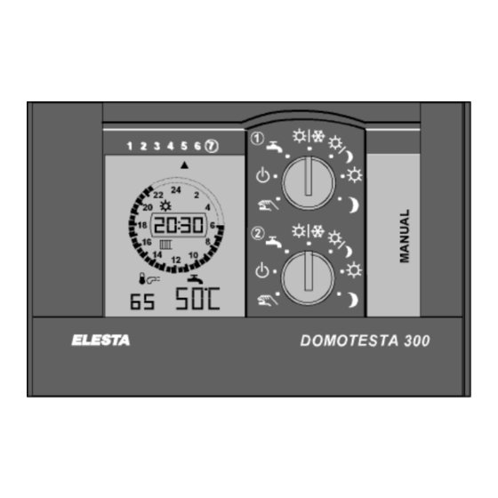
Page 6: Operating Elements
User manual: RDO3x3A Operating elements Mode switch=BA1 BA2 (temperature setpoint adjustment) Service interface (PC) Key " " : DHW charging Key " " : Increase value Key " " : Decrease value Key " " : Parameter selection Key " "... - Page 7 User manual: RDO3x3A 3.2.1 Display of special modes: Special modes can be superimposed to the program by using push-buttons at the controller or the remote control unit or via external inputs. Thus different temperature setpoints may be activated. Superimposed modes (flashing symbols): : Heating circuit : DHW heating circuit : Boiler circuit (heat generator)
-
Page 8: Operation Level L: Simple Operation Settings
User manual: RDO3x3A Error numbers and description: Sensor or function errors: 1..7 Heating circuit (1..7) = 11..14 Heat generator (burner 1..4) = 21..24 MCBA14..-errors (MCBA 1..4) A..d LMU64..-errors (LMU64 1..4) = 31..34 DHW circuit (1..4) Er ZZ_1 : DHW temperature sensor 1 defective (boiler) Er ZZ_2 : DHW temperature sensor 2 defective (boiler) Er ZZ_3... - Page 9 User manual: RDO3x3A Service mode 1: Burner on stage 1 or modulation command full power. Boiler pump is on. The mixing valve output (return) is in operation. DHW charge is permanently on Service mode 2: Burner on stage 2 or modulation command to minimum. Boiler pump is on. The mixing valve output (return) is in operation.
-
Page 10: Operation Level Ll: Advanced Operation Settings
User manual: RDO3x3A Operation level ll: Advanced operation settings Press key to select function 1 20.30 Additional symbols in the display Parameter value (LCD: Display at lower right) Parameter number (LCD: Display at lower left) 3.4.1 Operation at operation level ll Operation level II is activated by the function selector key. - Page 11 User manual: RDO3x3A 3.4.3 Holiday program 6 Holiday blocks can be programmed. Odd parameters (1, 3, 5, ...) represent absence start, (temperature setpoint “ =frost protection” or “ =reduced”) and even parameters (2, 4, 6, ...) represent the resume date (temperature setpoint “ =normal”). DHW charging is disabled, when all heating circuits are in frost protection mode (i.e.
- Page 12 User manual: RDO3x3A Add switching points: 3 - -.- - : Select next unused switching point "- -.- -" 3 16.00 : Set desired time; e.g. 16:00 " =normal" : Select next switching point 4 16.15 : Set desired time; e.g. 22:00 " =reduced" 4 22.00 Erase switching point: : Select even switching point...
- Page 13 User manual: RDO3x3A 3.4.6 Correct room temperature deviation If the actual room temperature deviates from the setpoint after several hours of operation, the internal reference can be adapted as follows: : Select function " " : Select heating circuit [ 1 20.3°C : Temperature is displayed 1 19.8°C...
- Page 14 User manual: RDO3x3A Additional data: 63.00 : Totalized 1: counter 1 x factor 1 (split indication: low value) 1130 High value: (at clock segment) [total: 113063.00] 93.00 : Totalized 2: counter 2 x factor 2 (split indication: low value) 0245 High value: [total=24593.00] : PWM1 (speed collector pump, output 0..10V, etc.) [%] Error list:...
-
Page 15: Installation
User manual: RDO3x3A Installation Controller 4.1.1 Dimensions max. 9 mm 4.1.2 Mounting Flush mounting: Slide device into panel cut-out and secure it with fastening bolts. Wire with connectors for AMP male connectors RZB500A and RZB501A, screw able connectors RZB510A and RZB511A (or base plate RZB520A with RZB511A). -
Page 16: Sensors
User manual: RDO3x3A Sensors 4.2.1 Remote control unit, room temperature sensors For residential area only. Not to be exposed to sun or other heat sources (chimney, radiators, draughts, TV-set, lamps); not behind furniture or curtains; ca. 1.2-1.5m height; seal installation conduit. Use breakthroughs in housing base for drilling the fixing points. - Page 17 User man nual: RDO3x3A 4.2.3 Passive tem mperature e sensors se flex cable e 2x1mm², un nshielded, se eparated from m mains lines s. Max. lengt th for passive e sensors 10 00m. inimize use o of conduit- o or connector boxes.
-
Page 18: Accessories
User manual: RDO3x3A Cable sensor RFT113B: (NTC 10kΩ; by 25°C) Cable sensor RFT203B: (PTC 1kΩ; by 25°C) RFT113B for primary temperature (Br) Mounting: With insertion pod (mounting depth min. 51mm). - RFT113B20 : L=2m Measuring range: -30..105°C (Br) - RFT203B40 : L=4m Measuring range: -30..105°C... -
Page 19: Terminal Assignment
User manual: RDO3x3A Bus interface RZB568A000 (RDO3x3A only): Plugs into back of controller (RDO3x3A only): RS485 : Connection of max. 63 controllers (slaves) to REN Bus or Modbus via cable, 2 wires, shielded, max. length 1200m, up to 500m: 0.5mm , up to 1000m: 1.0mm . -
Page 20: Terminal Designation
User manual: RDO3x3A Terminal designation Terminal Symbols Description number designation 230VAC: Inputs and outputs Neutral 2, 5, 12, 13 Phase (230VAC) Counter of operating hours burner stage 1 (230VAC) District heating with 1 HE: Qmin limitation Counter of operating hours burner stage 2 (230VAC) District heating with 2 HE: Qmin limitation 2, DHW Burner stage 2 ON / stage 1 modulation INCREASE... -
Page 21: Controller Rdo353A
User manual: RDO3x3A Terminal Description number Remote control unit for room temperature adaptation with sensor (on D-bus) Relay module: External relay: 12VDC; Ri > 600Ω (print relay recommended) RZM5xx Auxiliary module (on D-bus) Opto-coupler module for DHW thermostat (for galvanic separation) WW-Th DHW thermostat WW el. -
Page 22: Heating Circuit Module Rzm510A004
User manual: RDO3x3A Heating circuit module RZM510A004 (Br) Master controller device bus (D-Bus) 2-wires, invertible Ext.2 Ext.1 RZM510A004 Aux. input: Heating on standby Heating off, frost protection active Aux. input: Flow temperature setpoint Min. temperature setpoint active (automatic heating limiter operates on unrestricted flow setpoint) Boiler cascade module RZM530A004 Aux. -
Page 23: Dhw Module Rzm515A004
User manual: RDO3x3A DHW module RZM515A004 Master controller device bus (D-Bus) 2-wires, Bv2 Bww2 Bww1 invertible Ext.2 Ext.1 RZM515A00 WWTh WWel (WWel ) (WWZ (WWZ S1 : Aux. input: DHW heating on standby DHW heating OFF, frost protection active, DHW pump as set S2 : Aux. - Page 24 User manual: RDO3x3A Boiler cascade modules and gas boiler controller: Parameter Module Par.102=1..3 Address RZM530A Par.102=10 Address gas module Par.102=11 Address RZM530A Address gas module Internally controlled boiler Address for DHW modules: Addresses (2..4) may be assigned to the DHW modules RZM515A according their circuit number. DHW circuit 1 is controlled by the RDO3x3A.
- Page 25 User manual: RDO3x3A Warning: Address setting in RZM510A, RZM515A, RZM530A: - Disconnect the heating system completely from mains - Carefully open the cover using a screw driver (left side of mode switch) - Set required address using an insulated screw driver. - Put cover back into place Note: District heating with one heat exchanger (HE) - Stage 2: (6/7) for primary valve: (6) ON (increase return temperature)
-
Page 26: Checklists
User manual: RDO3x3A Checklists Initial start up • Set the parameters as required (see 7: Expert level I, parameter list). • Switch the mains OFF (remove mains fuses). • Before connecting the controller to the base plate or AMP connectors, check that the necessary devices (pumps, sensors, burner, mixing valve, etc.) are connected according wiring diagram. - Page 27 User manual: RDO3x3A Emergency operation general: If heat generator and pump are still working, set the mode switch to manual operation " ". Adapt boiler thermostat setting to the required flow temperature. Open the mixing valve by hand as necessary. Set mixing valve to "automatic".
-
Page 28: Expert Level L: Parameter Setting
User manual: RDO3x3A Expert level l: Parameter setting The expert level shall be accessed by authorised personnel only, that is trained for this device. Inappropriate modification of parameters may lead to faulty system behaviour and result in damage to system and devices. Access to expert level I: Activate function "Service"... - Page 29 User manual: RDO3x3A 2 Heat generator dual stage 3 Modulating heat generator (burner) 10 Gas module for burner 11 Gas module for burner and RZM530A (special) 21 Heat pump single stage 22 Heat pump dual stage Par 103 Flue gas temperature sensor 0 Without flue gas temperature sensor 1 With flue gas temperature sensor Par 104...
- Page 30 User manual: RDO3x3A 3 DHW pump (terminal 15) 4 Boiler circuit pump (terminal 8) 5 Mix circuit pump 1 (terminal 9) 6 Mixing valve 1 ON (terminal 10) 7 Mixing valve 1 OFF (terminal 11) 8 Mix circuit pump 2 (terminal 44) 9 Mixing valve 2 ON (terminal 42)
- Page 31 User manual: RDO3x3A Par 112 Mixing valve drive (characteristic) 2 2-point mixing valve drive is used (relay mixing valve_OPEN) 3 3-point mixing valve drive is used Par 113 Transition time of the mixing valve [min] 1..30 Transition time of the mixing valve drive (effective for 3-point action) Par 114 Heating circuit pump 1 0 Standard ON/OFF...
- Page 32 User manual: RDO3x3A Par 119 DHW modules (RZM515A) at device-bus Note: A total of 3 DHW circuits can be controlled by one RDO For address setting see chapter 5.7 0..3 Number of external DHW modules (RZM515) Par 11A Boiler circuit pump output (terminal 8) KK 0 Controlled by demand 1 Operate as buffer storage pump 2 Operate as buffer storage pump, deactivated for DHW charging...
- Page 33 User manual: RDO3x3A 25 Input for buffer storage temperature sensor 1 26 Input for buffer storage temperature sensor 2 (bottom) 27 Input for return temperature sensor (primary side of HE for DHW charge) 28 Input for solar collector temperature sensor 1 30 Input for DHW temperature sensor 1 40 Set heating circuit 2 to standby 41 Set heating circuit 2 to summer operation...
- Page 34 User manual: RDO3x3A Par 126 Input Bh2: Operating hours 2 (terminal 4) 230VAC input 0 Counter for operating hours burner 2 1 Signal: Burner malfunction 2 DHW thermostat 3 Release DHW electrical charge 4 Qmin-limiter for DHW district heating 69 Signal: Burner malfunction without operation stop 70 Block energy function after flow control deviation (Par.10n) 151..194 As in list of parameter 120 (RDO only) Par 127...
- Page 35 User manual: RDO3x3A Configuration of controller functions Par 130 Basic indication field 1 (format: -99..199) 0 No indication 1 DHW temperature (sensor Bww) 2 DHW temperature 2 (sensor bottom) 3 DHW temperature mixing valve 1 4 DHW temperature mixing valve 2 10 Outdoor temperature (sensor Ba) 12 Room temperature...
- Page 36 User manual: RDO3x3A Par 137 Baudrate for PC connection 600..9200 Baudrate (values: 600/1200/2400/4800/9600/9200=19200) Par 138 Controller address 1..200 Address of the controller for the RS232 interface Par 139 Remote setting of operation mode Note: Performed via RS232 Note: Local setting “manual”, “OFF”, or “standby” supersedes remote setting 0 Remote setting prohibited 1 Remote setting enabled 2 Remote setting enabled.
- Page 37 User manual: RDO3x3A Par 147 Modulation differential phase [s/K] 0..99 D-value TV[s]=Par.147 / xp xp: Par.144 Par 148 Modulating burner transition time [s] 10..120 Transition time of the drive Par 149 District heating bend point 1 (Ta) [°C] 0..30 Outdoor temperature at bend point 1 Par 14A District heating return temperature 1 [°C] 20..90...
- Page 38 User manual: RDO3x3A Configuration of limitations and boiler protection Par 150 Boiler temperature minimum limitation (Tkmin) [°C] 0..99 Minimum boiler temperature Par 151 Boiler temperature maximum limitation (Tkmax) [°C] 0..125 Maximum boiler temperature at DHW charging (boiler temperature sensor) Par 152 Boiler temperature maximal limitation (heating) [°C] 0..125 Maximum boiler temperature limit regular heating (boiler temperature sensor)
- Page 39 User manual: RDO3x3A Configuration of heating curve For boiler cascade or Tk [°C] Tksoll for fixed-value control: Par.162 Note: The boiler setpoint temperature can be modified using the keys „+,-„ at basic indication. When using the outdoor temperature sensor, it will be increased automatically as to the heating curve Par.160 Par.161...
- Page 40 User manual: RDO3x3A Par 169 Source of outdoor temperature K 1: 0 No outdoor temperature sensor used (room temperature control) 1 Outdoor temperature sensor 1 (Ba1) used 2 Outdoor temperature sensor 2 (Ba2) used 3 Mean value of outdoor temperature sensors 1 and 2 (Ba1, Ba2) used 4 Outdoor temperature sensor at heating circuit module RZM510 used 5 Outdoor temperature at BCB 6 Outdoor temperature at D-Bus...
- Page 41 User manual: RDO3x3A Par 181 Automatic summer/winter heating limit [K] Note: - Mode switch must be set to automatic mode. - When limit is active, the “sunshade” symbol appears on the display 0.0 OFF 0.5..10.0 Value for the automatic summer/winter heating limit Heating limit: The automatic short term heating limit is a short term economy function that switches off heating operation if the flow temperature setpoint is only ca.
- Page 42 User manual: RDO3x3A Par 192 Anti legionella function 0 Anti legionella function disabled 1..7 Weekly heating to setpoint “legionella” (1=Monday..7=Sunday) 8 Daily heating to setpoint “legionella” Par 193 Setpoint raise on DHW charge [K] 2..60 Setpoint raise on DHW charge (with DHW temperature sensor only) Par 194 Alternate boiler temperature setpoint on DHW charge [°C] 0..99...
- Page 43 User manual: RDO3x3A Par 19d Setpoint raise DHW mix-circuit 2 [K] Note: Set Par.116=16 0..99 Setpoint raise DHW mix-circuit 2/DHW mix circuit 1 Par 19E Transition time DHW mixer 1 [min] 1..30 Transition time DHW mixer 1 Par 19F Transition time DHW mixer 2 [min] 1..30 Transition time DHW mixer 2 Par 19h...
- Page 44 User manual: RDO3x3A Par 1Ab Volume flow rate of solar pump [l/h] 0..2000 Volume flow rate of solar pump at 100% speed Par 1Ac Specific heat capacity [kJ/l*K] 3.50..4.50 Specific heat capacity of fluid Par 1Ad Collector efficiency [%] 0..100 100=ideal energy transmission Par 1AF Collector absorber area [m...
-
Page 45: Expert Level Ll: System Test
User manual: RDO3x3A Expert level ll: System test Functions of level : Configuration of special functions Function test of relay and PWM outputs Function test of inputs Set and reset of operating hours: 1675 : Heat generator stage 1, total running time [hours] (Par.30) : Heat generator stage 2, total running time [hours] (Par.31) 2535 : Collector pump, total running time [hours] (Par.34) - Page 46 User manual: RDO3x3A Outputs that are allocated to heat generator: Burner Burner BrA with District 2-step modulating RZM530A heating Par. Terminal: Key: - / + - / + - / + - / + Burner 1 off / on off / on Burner 2 on/OPEN ¦...
-
Page 47: Abbreviations
User manual: RDO3x3A Abbreviations ; Ta : Outdoor temperature sensor ; Outdoor temperature (weather) ; Tag : Flue gas temperature sensor ; Flue gas temperature : Input running hours burner step 1 : Input running hours burner step 2 ; Tk : Boiler temperature sensor ;... -
Page 48: Protocol: Setpoints, Time Switch Program
User manual: RDO3x3A Protocol: Setpoints, time switch program, … Control unit Type: RDO SW-Version: Program switch Plant hydraulics Function aux. input Function input Bh Date/Name Heat generator 1 Plant hydraulics Date/Name Boiler cascade module 2 Type: RZM530A SW-Version: Plant hydraulics Function aux. - Page 49 User manual: RDO3x3A DHW 1 in RDO symbol 1 DHW-setpoint leg: Plant hydraulics Aux. input WW-Th: WWel: Weekday Monday Tuesday Wednesday Thursday Friday Saturday Sunday DHW circuit 2 Type: RZM515A symbol 2 DHW-setpoint leg: Plant hydraulics Aux. input WW-Th: WWel: Weekday Monday Tuesday...
- Page 50 User manual: RDO3x3A Free clock channel symbol 9 lit Weekday Monday Tuesday Wednesday Thursday Friday Saturday Sunday Heating circuit 1 symbol 1 lit Room setpoint Remote control unit Plant hydraulics Aux. input Weekday Monday Tuesday Wednesday Thursday Friday Saturday Sunday Heating circuit 2 symbol 2 lit...
- Page 51 User manual: RDO3x3A Heating circuit 4 symbol 4 lit Room setpoint Remote control unit Plant hydraulics Aux. input Weekday Monday Tuesday Wednesday Thursday Friday Saturday Sunday Heating circuit 5 symbol 5 lit Room setpoint Remote control unit Plant hydraulics Aux. input Weekday Monday Tuesday...
- Page 52 User manual: RDO3x3A Your representation: Your installer:...
Need help?
Do you have a question about the DOMOTESTA RDO353A series and is the answer not in the manual?
Questions and answers