Table of Contents
Advertisement
Quick Links
Advertisement
Table of Contents

Related Manuals for Quanser SRV02

Summary of Contents for Quanser SRV02
- Page 1 Rotary Motion Servo Plant: SRV02 SRV02 Gyroscope User Manual...
- Page 2 SRV02 Gyroscope User Manual How to contact Quanser: +1 (905) 940-3575 Telephone +1 (905) 940-3576 Facsimile 119 Spy Court Markham, ON Mail Canada L3R 5H6 http://www.quanser.com mailto://info@quanser.com General information MATLAB is a registered trademarks of The MathWorks, Inc. Other brands and their products are trademarks or registered trademarks of their respective holders and should be noted as such.
-
Page 3: Table Of Contents
SRV02 Gyroscope User Manual Table of Contents 1. P ............................1 RESENTATION 2. SRV02 ..................2 YROSCOPE LANT OMPONENTS 2.1. Component Nomenclature........................2 2.2. Component Description........................3 2.2.1. Disk/Rotor..............................3 2.2.2. DC motor ...............................3 2.2.3. Inner frame.............................4 2.2.4. Encoder for inner frame rotation measurement ..................4 2.2.5. - Page 4 SRV02 Gyroscope User Manual 6.2. Encoder ............................10 6.2.1. Testing..............................10 6.2.2. Troubleshooting...........................10 7. T ..........................10 ECHNICAL UPPORT 8. R ............................10 EFERENCES Document Number 908 ♦ Revision 1.1 ♦ Page iii...
-
Page 5: Presentation
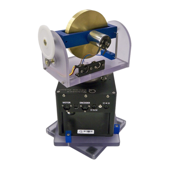
The SRV02 plant is mounted on a 2-plate structure. This structure consists of two plates mounted on top of each other that are free to rotate on top of each other. This allows the SRV02 plus gyroscope structure to be manually rotated relative to a fixed surface. Such an action can be thought of as an external disturbance that one might apply to the gyroscope system. -
Page 6: Srv02 And Gyroscope Plant Components
2. SRV02 and Gyroscope Plant Components The SRV02 plus gyroscope components are identified in Section 2.1. Some of these components are then described in Section 2.2. 2.1. Component Nomenclature The main components of the rotary gyroscope system are labeled below in Figure 2 and listed in Table 1. -
Page 7: Component Description
SRV02 Gyroscope User Manual Figure 2: SRV02 plus gyroscope module system components 2.2. Component Description 2.2.1. Disk/Rotor The rotor is used to acquire angular momentum for rotational dynamics experiments by spinning about its spin axis. 2.2.2. DC motor This component is depicted by #2 in Table 1 and Figure 2 and is used to rotate the disk (component #1). -
Page 8: Inner Frame
These components are identified with ID #10 in Table 1 and Figure 2 and are used to tighten the SRV02 plant to the base support plates. This can be done by using an Allen key to tighten the screws of each clamp. -
Page 9: Gyroscope Rotation Disk Motor Connectors
1. Setup the SRV02 in the high-gear configuration as explained in [5]. 2. Place the gyroscope module on top of the SRV02 plant such that the servo output shaft inserts the hole on the bottom platform of the gyroscope module and it can freely rotate about the shaft. -
Page 10: Wiring Procedure
Experiment Platform: Quanser SRV02 with Gyroscope module ● 5.1. Cable Nomenclature Table 3 provides a listing of the standard cables shipped with and used in the wiring of the SRV02 and gyroscope system: Cable Designation Description This cable connects an analog output of the data acquisition terminal board to the power module for proper power amplification. -
Page 11: Typical Connections
Table 3: Cable Nomenclature 5.2. Typical Connections This section describes the typical connections used to connect the SRV02 gyroscope plant to a data- acquisition board and the amplifier. The connections are illustrated in Figure 3 and summarized in Table 4. The details of the wiring procedure are given thereafter. -
Page 12: Connection Details
Please follow the steps below to wire the SRV02 gyroscope system: 1. Before proceeding with the connections, make sure the Quanser HIL board is already installed as discussed in [3]. If another data-acquisition device is being used, e.g. NI M-Series board, please consult the appropriate documentation to ensure that the board is installed properly. -
Page 13: Testing And Troubleshooting
This section describes some functional tests to determine if your SRV02 is operating normally. It is assumed that the SRV02 is connected as described earlier. To carry out these tests, it is preferable if the user can use a software such as QUARC or LabVIEW to read sensor measurements and feed voltages to the motor. - Page 14 Note: Some data acquisition systems do not measure in quadrature and, in this case, one-quarter of the expected counts are received, i.e. 256 counts in the SRV02-E or 512 in the SRV02-EHR. In addition, some data acquisition systems measure in quadrature but increment the count by 0.25 (as opposed to having an integer number of counts).
Need help?
Do you have a question about the SRV02 and is the answer not in the manual?
Questions and answers