Advertisement
Quick Links
Video Cassette Recorder
Service
Service
Service
Service Manual
Contents
Chapter
Sec. 1:
Adjustment Procedure
Schematic Diagrams and CBA's
Exploded Views
Mechanical and Electrical Parts Lists
Sec. 2: Standard Maintenance
Mechanism Alignment Procedures
Disassembly / Assembly of Mechanism
Deck Exploded Views
For technical data reference is made to the Service Manual of VR530/02/07/16 3103 785 21990.
The present Manual states only the differences.
Safety regulations require that the set be restored to its original
condition and that parts which are identical with those specified
be used.
Published by BK 2002 Video Service Department
VR130
Survey of versions:
/02
PAL B/G, VPS/PDC
/07
PAL I, Ireland
/16
PAL B/G, Spain
/39
SECAM L,L' & PAL B/G, I
/58
PAL/SECAM B/G, D/K
Printed in the Netherlands
c Copyright reserved
/02/07/39/58
Subject to modification
GB
3103 785 22100
Advertisement

Related Manuals for Philips VR130/02


Summary of Contents for Philips VR130/02
- Page 1 Video Cassette Recorder Service VR130 /02/07/39/58 Service Service Service Manual Contents Survey of versions: PAL B/G, VPS/PDC Chapter PAL I, Ireland PAL B/G, Spain Sec. 1: Adjustment Procedure Schematic Diagrams and CBA's SECAM L,L' & PAL B/G, I Exploded Views PAL/SECAM B/G, D/K Mechanical and Electrical Parts Lists Sec.
- Page 2 STATUS/EXIT To access or remove the VCR’s on- screen status display. To exit on-screen menus. Or, to access or remove a status display or menu of Philips 0..9 Press to select channels at VCR or Philips TV. MUTE To eliminate the TV’s sound.
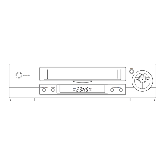
- Page 3 Front of the device STILL STANDBY/ON COUNTER RESET RECORD PROGRAMME PWR. STANDBY/ON To switch off or on, interrupt a function. PROGRAMME+ PROGRAMME- To select the programme number. During normal playback, press to adjust the tracking. RECORD To record the TV channel selected at this moments.
- Page 4 [ VR130/02, VR130/07, VR130/39, VR130/58 ] Signal Name Function Signal Name Function D-CONT Drum Motor Control Signal SCART 1 8Pin Output Control 8POUT-1 Drum Motor Rotation Detection Signal D-FG Pulse A-IN-1,2 Audio Signal Input 1, 2 D-PG Drum Motor Pulse Generator...
- Page 5 Signal Name Function P-ON Power Detection Input POW-SAF Signal Recording Safety SW Detect (With REC-SAF-SW Record tab="L"/With out Record tab="H") Remote REMOCON-IN Control Sensor System Reset RESET Signal (Reset=”L”) RF-SW Video Head Switching Pulse RGB- SCART 2 RGB Through Control THROUGH Signal SC2-IN...
-
Page 6: Block Diagrams
:USED TO INDICATE A TEST POINT WITH NO TEST PIN. " " = SMD HOLES OF THE PCB. :USED TO INDICATE A TEST POINT WITH A TEST PIN. Model Mark (WIRE IS SOLDERED DIRECTLY.) VR130/02 FUNCTION CBA VR130/07 MAIN CBA TP507 IC501 VR130/39 (SERVO/SYSTEM CONTROL) -
Page 7: Video Block Diagram
2. PREFIX SYMBOL "CL" MEANS WIRE-SOLDER :USED TO INDICATE A TEST POINT WITH NO TEST PIN. " " = SMD VR130/02 HOLES OF THE PCB. :USED TO INDICATE A TEST POINT WITH A TEST PIN. (WIRE IS SOLDERED DIRECTLY.) VR130/07... - Page 8 :USED TO INDICATE A TEST POINT WITH NO TEST PIN. HOLES OF THE PCB. Model Mark :USED TO INDICATE A TEST POINT WITH A TEST PIN. (WIRE IS SOLDERED DIRECTLY.) PB-AUDIO SIGNAL REC-AUDIO SIGNAL Mode : SP/REC VR130/02 VR130/07 MAIN CBA TU701 VR130/39 VR130/58 TU-AUDIO AF,AG,AI J984...
- Page 9 REPLACE ONLY WITH THE SAME TYPE T1.6AL/250V FUSE. circuit are not defective before you connect the AC plug to the AC power supply. Model Mark Otherwise it may cause some components in the power supply circuit to fail. VR130/02 VR130/07 MAIN CBA VR130/39 HOT CIRCUIT. BE CAREFUL.
- Page 10 REC MODE Pin No. MODEL MARK MODEL MARK KEY 1 (7PIN) KEY 2 (8 PIN) (2.5) Voltage VR130/02 VR130/39 INDICATES THAT THE VOLTAGE THE SAME VOLTAGE FOR VR130/07 VR130/58 0.00 ~ 0.51V POWER CH UP BOTH PLAY & REC MODES.
- Page 11 Models and Marks (2.5) INDICATES THAT THE VOLTAGE MODEL MARK THE SAME VOLTAGE FOR BOTH PLAY & REC MODES. IS NOT CONSISTENT HERE. VR130/02 “ “ = SMD VR130/07 VR130/39 VR130/58 MAIN 2/5 Schematic Diagram Parts Location Guide Ref No.
- Page 12 Models and Marks (2.5) INDICATES THAT THE VOLTAGE THE SAME VOLTAGE FOR MODEL MARK BOTH PLAY & REC MODES. IS NOT CONSISTENT HERE. VR130/02 “ “ = SMD VR130/07 VR130/39 VR130/58 MAIN 3/5 Schematic Diagram Parts Location Guide Ref No.
- Page 13 Main 4/5 Schematic Diagram Comparison Chart of Models and Marks MODEL MARK VR130/02 VR130/07 VR130/39 VR130/58 NOTE : CAUTION ! MODE: SP/REC PLAY MODE REC MODE THE VOLTAGE FOR PARTS IN HOT CIRCUIT IS MEASURED USING Fixed voltage (or Auto voltage selectable ) power supply circuit is used in this unit.
- Page 14 Models and Marks (2.5) INDICATES THAT THE VOLTAGE MODEL MARK THE SAME VOLTAGE FOR IS NOT CONSISTENT HERE. BOTH PLAY & REC MODES. VR130/02 VR130/07 VR130/39 VR130/58 MAIN 5/5 Schematic Diagram Parts Location Guide ( AH ) Ref No. Position...
- Page 15 Function Schematic Diagram Comparison Chart of Models and Marks MODEL MARK “ “ = SMD VR130/02 VR130/07 VR130/39 VR130/58 HC260SCF Function Schematic Diagram Parts Location Guide Ref No. Position CONNECTOR CN651 RESISTORS R651 R652 R653 R654 R655 SWITCHES SW651 SW652...
- Page 16 Models and Marks MODE: SP/REC “ “ = SMD PLAY MODE REC MODE MODEL MARK (2.5) VR130/02 INDICATES THAT THE VOLTAGE THE SAME VOLTAGE FOR VR130/07 IS NOT CONSISTENT HERE. BOTH PLAY & REC MODES. VR130/39 VR130/58 Jack Schematic DiagramParts Location Guide Ref No.
- Page 17 Main CBA Parts Location Guide Ref No. Position Ref No. Position Ref No. Position Ref No. Position Ref No. Position Ref No. Position Ref No. Position Ref No. Position Ref No. Position CAPACITORS CAPACITORS CAPACITORS CONNECTORS COILS RESISTORS RESISTORS RESISTORS RESISTORS C002 C326...
- Page 18 Main CBA Top View BECAUSE A HOT CHASSIS GROUND IS PRESENT IN THE POWER CAUTION ! SUPPLY CIRCUIT , AN ISOLATION TRANSFORMER MUST BE USED. Fixed voltage (or Auto voltage selectable ) power supply circuit is used in this unit. ALSO , IN ORDER TO HAVE THE ABILITY TO INCREASE THE INPUT CAUTION If Main Fuse (F001) is blown, check to see that all components in the power supply...
- Page 19 Main CBA Bottom View BECAUSE A HOT CHASSIS GROUND IS PRESENT IN THE POWER CAUTION ! SUPPLY CIRCUIT , AN ISOLATION TRANSFORMER MUST BE USED. Fixed voltage (or Auto voltage selectable ) power supply circuit is used in this unit. ALSO , IN ORDER TO HAVE THE ABILITY TO INCREASE THE INPUT CAUTION If Main Fuse (F001) is blown, check to see that all components in the power supply...
- Page 20 Function CBA Bottom View Function CBA Top View Function CBA Parts Location Guide Ref No. Position Ref No. Position CONNECTORS SWITCHES CN651 SW651 RESISTORS SW652 R651 SW653 R652 SW654 R653 SW656 R654 R655 BHC400F01017-B Power SW CBA Top View Power SW CBA Bottom View BHC400F01017-D 1-10-77 1-10-78...
- Page 21 Jack CBA Top View JACK CBA Parts Location Guide Ref No. Position Ref No. Position CAPACITORS RESISTORS C102 R101 C104 R102 C105 R105 C107 R106 C108 R108 C109 R109 C112 R110 C113 R111 C115 R114 Jack CBA Bottom View C116 R115 C117 R116...
- Page 22 AC CORD Models & Marks (CAN DISCONNECT AND RECONNECT.) 2. PREFIX SYMBOL "CL" MEANS WIRE-SOLDER Model Mark HOLES OF THE PCB. (WIRE IS SOLDERED DIRECTLY.) ANT-IN ANT-OUT VR130/02 VR130/07 VR130/39 SENSOR CBA VR130/58 (BHB300F01011) SENSOR CBA (BHB300F01011) (DECK ASSEMBLY) CL151...
- Page 23 [ VR130/02, VR130/07, VR130/39, VR130/58 ] EJECT ST-S,/ END-S "OFF" CASS.LOAD LD-FWD 0.2S LD-REV 0.7S LD-FWD 0.2S LD-REV 0.2S LD-FWD 0.5S LD-REV STOP(A) PLAY LD-FWD PLAY LD-FWD LD-REV 0.2S LD-FWD PLAY PLAY PAUSE STILL PAUSE ON NOISE CANCEL PAUSE STILL...
- Page 24 STOP(A) STOP LD-REV 0.2S LD-FWD STOP /EJECT LD-REV 2.0S LD-FWD 0.5S LD-REV STOP(A) LD-REV 0.2S LD-FWD STOP /EJECT LD-REV 2.0S LD-FWD 0.5S LD-REV STOP(A) LD-FWD PAUSE LD-FWD 2.5S Short REV LD-REV 0.2S LD-FWD REC PAUSE REC or PAUSE STOP /EJECT LD-FWD 1.5S LD-REV...
- Page 25 [ VR130/02, VR130/07, VR130/39, Signal Active Mark Function Name Level VR130/58 ] Color Phase Rotary OUT C-ROTA Comparison Chart of Models and Marks Changeover SIgnal Model Mark N.U. Not Used VR130/02 N.U. Not Used VR130/07 Video Head OUT RF-SW Switching Pulse VR130/39 N.U.
- Page 26 Signal Active Signal Active Mark Function Mark Function Name Level Name Level Recording Safety N.U. Not Used SW Detect (With REC- Record tab="L"/ SAF-SW SECAM or With out Record MESECAM tab="H") COLOR- Chroma Video Input Signal at Super Impose N.U. Not Used N.U.
- Page 27 Signal Active Mark Function Name Level PULS Take Up Reel T-REEL Rotation Signal H/L/ OUT LM-FWD/ Loading Motor Control Signal Hi-z N.U. Not Used Audio Mute OUT A-MUTE- Control Signal (Mute = “H”) N.U. Not Used N.U. Not Used Power Voltage Down Detector DOWN-L Signal...
- Page 28 [ VR130/02, VR130/07, VR130/39, VR130/58 ] 2SC1815-Y(TPE2) FS1KM-18A BN1F4M-T 2SC1815-GR(TPE2) FS1KM-14A BA1F4M-T 2SC2120-Y(TPE2) KTA1266(GR) KTC3203(Y) KRA104M 2SC1815-BL(TPE2) KTC3199(Y,GR,BL) 2SC2785(J.H.F.K) KRA103M KRC103M BN1L4M-T 2SA1015-GR(TPE2) G D S E C B E C B CAT24WC02JI LA71750AM-MTB TC4052BF(EL) BR24C02F-W QSZAB0RMB098 BU4052BCF-E2 AT24C02N-10SC CD4052BCSJX M24C02-MN6T LTV-817(B.C)-F...
-
Page 29: Electrical Parts List
PRODUCT SAFETY NOTE: Products marked with a h have special characteristics important to safety. Before replacing any of these components, read carefully the product safety notice in this service manual. Don't degrade the safety of the product through improper servicing. NOTES: Parts that not assigned part numbers (-----------) are not available. - Page 30 ELECTRICAL PARTS LIST Pos. 12 NC Description C158 CHIP CERAMIC CAP. B K 1000PF/50V C159 CHIP CERAMIC CAP. F Z 0.1UF/50V C251 ELECTROLYTIC CAP. 10UF/16V M H7 C252 CHIP CERAMIC CAP. B K 1000PF/50V C253 ELECTROLYTIC CAP. 1UF/50V M H7 C254 CHIP CERAMIC CAP.
- Page 31 ELECTRICAL PARTS LIST Pos. 12 NC Description C381 CHIP CERAMIC CAP. F Z 0.1UF/50V C382 CHIP CERAMIC CAP. B K 2200PF/50V C383 CHIP CERAMIC CAP. B K 2200PF/50V C384 ELECTROLYTIC CAP. 2.2UF/50V M H7 C401 ELECTROLYTIC CAP. 47UF/6.3V M H7 C402 ELECTROLYTIC CAP.
- Page 32 ELECTRICAL PARTS LIST Pos. 12 NC Description C702 CHIP CERAMIC CAP. F Z 0.1UF/50V C703 ELECTROLYTIC CAP. 10UF/16V M H7 C704 CHIP CERAMIC CAP. B K 0.01UF/50V C706 CHIP CERAMIC CAP. B K 1000PF/50V C707 ELECTROLYTIC CAP. 100UF/6.3V H7 C708 CHIP CERAMIC CAP.
- Page 33 ELECTRICAL PARTS LIST Pos. 12 NC Description IC001 4822 130 11655 PHOTOCOUPLER LTV-817B-F IC151 5322 209 17147 IC:SWITCHING TC4052BF(EL) IC301 9965 000 12180 IC:Y/C/A LA71750AM-MTB IC370 9965 000 12255 IC:SECAM LA70100M-TRM IC501 9965 000 13787 MICROCONTROLLER 16BIT M37762MCA-1A6GP IC503 9965 000 06554 IC:MEMORY BR24C02F-W IC561 9965 000 12183 IC:LED DRIVER PT6958-FN-TP J902...
- Page 34 ELECTRICAL PARTS LIST Pos. 12 NC Description R003 CARBON RES. 1/4W J 1M OHM R004 CARBON RES. 1/4W J 1M OHM R005 CARBON RES. 1/6W G 1.5K OHM R006 METAL OXIDE FILM RES. 1W J 2.2 OHM R007 CARBON RES. 1/6W J 22K OHM R008 CARBON RES.
- Page 35 ELECTRICAL PARTS LIST Pos. 12 NC Description R320 CHIP RES.(1608) 1/10W J 560 OHM R321 CARBON RES. 1/6W J 33 OHM R323 CARBON RES. 1/6W J 33 OHM R324 CHIP RES.(1608) 1/10W J 39K OHM R328 CHIP RES.(1608) 1/10W J 1K OHM R330 CHIP RES.(1608) 1/10W J 5.6M OHM R331...
- Page 36 ELECTRICAL PARTS LIST Pos. 12 NC Description R513 CHIP RES.(1608) 1/10W J 1.8K OHM R514 CHIP RES.(1608) 1/10W J 820 OHM R516 CHIP RES.(1608) 1/10W J 330K OHM R517 CHIP RES.(1608) 1/10W J 220 OHM R518 CHIP RES.(1608) 1/10W J 470 OHM R519 CHIP RES.(1608) 1/10W 0 OHM R520...
- Page 37 ELECTRICAL PARTS LIST Pos. 12 NC Description SW504 4822 276 13954 TACT SWITCH KSM0614B SW505 4822 276 13954 TACT SWITCH KSM0614B SW506 9965 000 12192 LEAF SWITCH MXS00052MPP0 SW507 9965 000 09194 ROTARY MODE SWITCH R8100212 T001 9965 000 09203 PULSE TRANS SA-00901B TP301 PCB JUMPER D0.6-P9.5 TP501...
- Page 38 ELECTRICAL PARTS LIST Pos. 12 NC Description L101 4822 526 10685 BEAD CORE B16 RH 3.5X10X1.3 L121 4822 526 10685 BEAD CORE B16 RH 3.5X10X1.3 TRANSISTORS Q101 4822 130 42959 TRANSISTOR KTA1266(GR) Q102 4822 130 42959 TRANSISTOR KTA1266(GR) RESISTORS R101 CARBON RES.
- Page 39 [ VR130/02, VR130/07, VR130/39, VR130/58 ] Front Panel 1-17-4 HC260FEX...
- Page 40 [ VR130/02, VR130/07, VR130/39, VR130/58 ] Cabinet 2L011 2B18 2L011 2L011 2L011 JACK CBA 2L011 2L012 2L022 2L042 2L021 2L021 2L022 2L022 2L021 2L051 2L022 2L021 2L041 2L021 SENSOR CBA 2L041 POWER SW CBA 2L041 2L031 2B14 MAIN CBA 2L099...
- Page 41 [ VR130/02, VR130/07, VR130/39, VR130/58 ] Packing Some Ref. Numbers are not in sequence. [ AF,AH,AI ] X20A X20B X20C [ AF ] X20G X20H X20I [ AF,AI ] X20D X20E X20F X20J X20K [ AH ] [ AG ]...
-
Page 42: Mechanical Parts List
PRODUCT SAFETY NOTE: Products marked with a h have special characteristics important to safety. Before replacing any of these components, read carefully the product safety notice in this service manual. Don’t degrade the safety of the product through improper servicing. MECHANICAL PARTS LIST Pos. - Page 43 [ VR130/02, VR130/07, VR130/39, VR130/58 ] Before following the procedures described below, be sure to remove the deck assembly from the cabinet. (Refer to CABINET DISASSEMBLY INSTRUCTIONS on page 1-7-1.) All the following procedures, including those for adjustment and replacement of parts, should be done in Eject mode;...
- Page 44 REMOVAL INSTALLATION STEP START- REMOVE/*UNHOOK/ /LOC. PART ADJUSTMENT Fig. No. UNLOCK/RELEASE/ CONDITION UNPLUG/DESOLDER [34] [2],[25] M Brake S Assembly DM1,DM16 *(P-7) Tension Lever Sub [35] [34] DM1,DM16 Assembly [36] [35] T Lever Holder DM1,DM16 *(L-6) [37] [33] M Gear DM1,DM16 (C-6) [38] [2],[15] Sensor Gear DM1,DM16 (C-7)
-
Page 45: Top View
Top View [41] [42] [46] [43] [14] [13] [11] [15] [35] [36] [10] [12] [34] [33] [40] [29] [38] [37] [39] Fig. DM1 Bottom View [19] [32] [31] [24] [26] [27] [25] [23] [28] [22] [20] [21] [30] Fig. DM2 2-4-13 HC260DA... - Page 46 (S-1) (S-1) (S-2) (P-1) (S-3) (S-4) Fig. DM5 Fig. DM3 [46] Type A Pin D Type B [47] Pin C [46] (L-9) Pull up Slide Pin A (L-8) Pin B Slot A Slots B (S-5) Slot A First, while pushing the locking tab as shown in the right, slide and pull up the right side on [2] to release Pin A and Pin B from the slots A.
- Page 47 (S-7) (S-8) [14] (S-9) [15] Desolder from bottom (S-6) Lead with White Stripe Belt View for A Fig. DM7 Fig. DM9 Adj. Screw [17] After removing the Screw (S-10), [11] while pressing the Locking Tab (L-1) (L-3) (L-2) (L-3), remove [16]. (P-3) [16] [13]...
- Page 48 Cap Belt Portions A on [21] must be set in the slot on [20] as shown. (C-1) [19] [20] Portions A Portions A View for A [21] Fig. DM12 (S-11) Fig. DM11 2-4-16 HC260DA...
- Page 49 [25] (C-2) (C-5) (C-3) [22] [23] (S-12) (P-4) [27] (L-4) (C-4) [26] [28] [24] (P-4) [28] When installing [23], install the spring (P-4) to [28] as Position of Mode Lever when installed shown in the left figure, and then install [23] while Pin on Pin of [34] Pin of [30]...
- Page 50 Refer to the Alignment Section, Page 2-4-19. [42] [41] [43] (P-5) [30] (L-7) [32] [29] [31] (L-5) Fig. DM17 Fig. DM15 [35] (C-7) [38] (C-6) (P-7) [40] [37] turn (L-6) [39] [44] [45] Slide (P-6) [34] turn [33] [36] Fig. DM18 turn Fig.
- Page 51 [ VR130/02, VR130/07, VR130/39, VR130/58 ] The following procedures describe how to align the Alignment 1 individual gears and levers that make up the tape Loading Arm, S and T Assembly loading/unloading mechanism. Since information about the state of the mechanism is provided to the...
- Page 52 Alignment 3 Cam Gear (A), Rack Assembly Install the Rack Assembly so that the first tooth on the gear of the Rack Assembly meets the first groove on the Cam Gear (A) as shown in Fig. AL4. Top View Cam Gear (A) Alignment 3 First tooth First groove...
- Page 53 [ VR130/02, VR130/07, VR130/39, VR130/58 ] Deck Mechanism View 1 Mark Description Part No. (Blue grease) Floil G-374G 0VZZ00109 SLIDUS OIL #150 0VZZ00226 L1467 B494 B553 L1191 B411 B567 L1053 B410 L1051 Chassis Assembly Top View (Lubricating Point) B501 B560...
- Page 54 Deck Mechanism View 2 Mark Description Part No. B587 Note: Both TENSION Floil G-374G (Blue grease) 0VZZ00109 LEVER ASSEMBLY MK11(B27) and the TENSION SANKOUL FG84M (Yellow grease) 0VZZ00062 LEVER ASSEMBLY MK11 (B587) can be used. B574 B508 B148 B487 B573 L1406 B522 B518...
- Page 55 Deck Mechanism View 3 Mark Description Floil G-374G (Blue grease) L1321 B347 Note: There are two different, but interchangeable types of CLEANER LEVER(B359) in this model, and have different combination with B361. Please L1321 see Table 1 for details and combination. (Refer to DECK PARTS LIST section on page 2-6-1.) Table 1 (B359 and B361 Combination) B359 CLEANER LEVER...
- Page 56 DECK PARTS LIST DECK PARTS LIST Pos. 12 NC Description Pos. 12 NC Description CYLINDER ASS. 9965 000 12895 B514 9965 000 12228 SCREW RACK MK11 MK11 PAL 2HD 2SP CYLINDER ASS. 9965 000 12909 B516 9965 000 05342 REEL WASHER MK9 5*2.1*0.5 MK11 PAL 2HD 1SP / for VR130/39 9965 000 12202 LOADING MOTOR ASS.
Need help?
Do you have a question about the VR130/02 and is the answer not in the manual?
Questions and answers