Table of Contents
Advertisement
Advertisement
Table of Contents

Summary of Contents for Pierce Glas
- Page 1 Glás Non Boiler Insert INstallatIoN & operatING INstructIoNs...
-
Page 2: Technical Data
table of content page no: Technical data . . 1/2 General Information . . 3/6 Installation Instructions . 7/8 Operating Instruction . Exploded View/ Parts Listing . 10 techNIcal Data: stoVe DIMeNsIoNs Front View left View top View 396 mm 494 mm 494 mm 398 mm... -
Page 3: Technical Data
All Pierce Stoves are accompanied by Both an installation manual with technical data and a manual on general use and maintenance. Only after a qualified inspector inspects an installation, it can be used. All Pierce Stoves have a name plate of heat -resistant material affixed. -
Page 4: General Information
Pierce Stove. If an air vent is fitted it must not be obstructed for any reason when the stove is in use. An extractor fan should not be fitted in the same room as your stove as fumes may emit into the room. -
Page 5: Distance To Combustibles
DIstaNce to coMBustIBles Pierce Stove insert stoves operate at high temperatures and are designed for installation into an existing fireplace. For safe operation of your Pierce Stove there are minimum distances to combustible materials, including wood and Plaster board, that must be adhered to at all times. These distances are as follows (see below diagram also) -
Page 6: Chimney Fire
chIMNeY FIre It is unlikely you will ever experience a chimney fire if your stove is installed and operated correctly as per the operation instructions. In the unlikely event of a chimney fire close the primary air and secondary air controls immediately, evacuate the building and call the Fire Service. - Page 7 Fault FINDING INstructIoNs problem probable cause action -use the recommended Wood green, too damp fuel. Fire difficult to start -to light the fire, use poor quality small, very dry kindling. to maintain the fire, use logs are too big split logs. -open primary air and secondary air Fire goes out...
-
Page 8: Installation Instructions
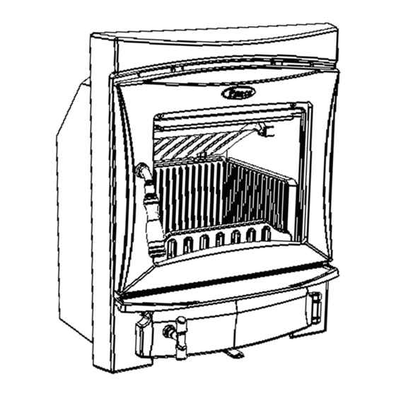
INstallatIoN INstructIoNs: step 1 Open the stove door and remove all loose packed parts, ashpan, tools and accessories. step 2 Disassemble the internal parts in the following order. 1. Fire Fence 2. Left and Right Side Castings 3. Loose Top Baffle 4. -
Page 9: Operating Instructions
step 6 Lift the still disassembled stove into the convection chamber approximately 50mm, lift the front edge to prevent damage to the hearth then slide it gently home to its final position step 7 The flue liner can now be fixed to the spigot (part 13 in parts listing) with the fixings provided and sealed according to the manufactures instructions. -
Page 10: Lighting The Stove
operatING INstructIoNs: prIMarY aIr coNtrol slIDer ValVe The primary air control slider is positioned underneath the ashpan door (see diagram above left). This slider controls the intake of primary air underneath the grate, slide to the right to increase the rate of burn and to the left to decrease the rate of burn. - Page 11 Glas INsert stoVe eXploDeD VIeW 1. Fire Fence PS10120 19. Axial Fiber CAL0103 2. Ash Baffle PS10162 20. Combustion Chamber CANK01 3. Ashpan Door PS10108 21. Handle CA0114-083 4. Fire door PS10107 22. Fiberglass rope CA0802 5. Front Frame PS10103 23.
- Page 12 Unit 2 Whitemill Industrial Estate Wexford Co Wexford www.piercestoves.ie Email: info@piercestoves.ie...
Need help?
Do you have a question about the Glas and is the answer not in the manual?
Questions and answers