
Summary of Contents for Hushon CW200
- Page 1 HUSHON CHILLED WATER CASSETTE MODELS CW200 ~ 701/C/D/A INSTALLATION MANUAL Revised Oct 2013...
- Page 5 200-300-400 500-600-701 14,8 16,5 16,5 37,1 37,1 39,6 * Weights refer to base units without valve.
- Page 6 MAX 200 mm...
- Page 7 Max 2 chiusure Max. 2 louvres closed Max 2 fermetures Max. 2 Luftauslässe geschlossen Máximo dos rejillas cerradas Max. 2 schoepen gesloten Máximo duas grelhas fechadas Max 2 luftspridare stängda Enintään kaksi tuuletusaukkoa Maks. 2 zamknięcia макс. 2 жалюзи закрыты...
- Page 9 mod. 200-300-400 mod. 500-600-701 mod. 200-300-400 mod. 500-600-701...
- Page 12 CCN STATUS...
- Page 14 400/500...
- Page 15 I II LEGEND / TABLE I Nominal data A = Power input 0,33 0,28 B = Models 0,29 0,25 C = Cooling D = Heating 0,46 0,42 E = Cooling (For 230V ~ 60Hz 0,32 0,27 versions) 0,52 0,48 F = Heating (For 230V ~ 60Hz 0,69 0,64 versions)
- Page 16 1,38 2,76 2,76 2,76 10,0 10,0 12,0 12,0 12,0 LEGEND / TABLE III - Technical data of electric heaters (if installed) A = Models B = Electric heater capacity C = Supply voltage (ph) D = Max. power input E = Safety thermostat F = N°...
- Page 17 III IV Description Q.ty Installation instructions Unit installation Table IV: Material supplied Valve insulating shell (only units with factory-installed valves) Gaskets (only units with factory-installed valves) Insulating Valves Clips (only units with factory-installed valves)
- Page 18 IV V Table V: Operating limits Minimu m entering water temperature: + 4°C Water- side maximum pressure Water circuit 1400 kPa (142 m w.c.) Maximum entering water temperature: + 80°C Minimum temperature: 5°C Room air Maximum temperature 32°C 230V ~ 50Hz Nominal single phase voltage Power supply min.
- Page 19 V VI Size / Code Size / Code Size / Code Description Description Description Small Large Small Large Small Large Kit Frame/grill 42GW9001 42GW9002 40GK-900--- 40GK-900--- I.R. control 33HDB-HR Air supply obstruction kit (*) 003-40 013-40 Kit Frame/grill 42GW9011 42GW9012 I.R.
- Page 20 Table • • • • • • • • • • • • • • • • 230V ~ 50Hz LEGEND / TABLE VII A = Models B = Sizes C = 2 pipes D = 4 pipes EH = electric heaters...
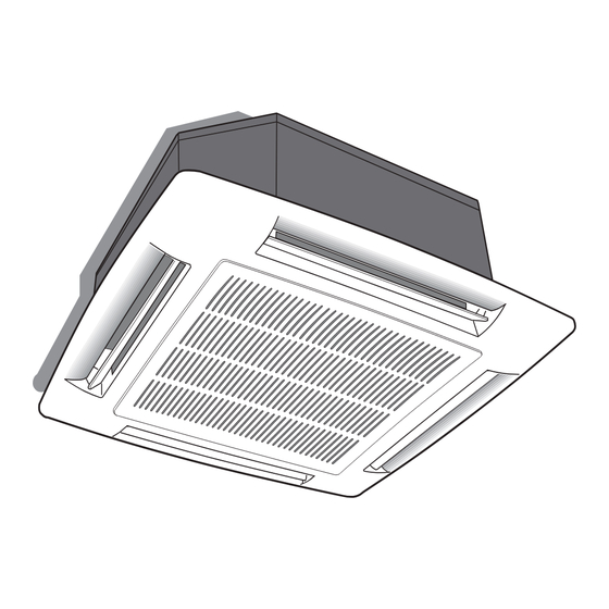
- Page 21 “Hydronic Global Cassette” Fan Coil Units Fig. 1. Fig. 35. BLACK - Unit Electrical box - Frame/Grille assembly Cable holder Fig. 40e. Terminal block Fig. 15. Electric heater relay Winter operation diagram with fresh air intake Capacitor Antifreeze thermostat Heating: louvre position for correct air Fusible Speed controller flow...
-
Page 22: General Information
General Information Unit installation • The manufacturer declines any liability for damage resulting from modifications or errors in the electrical or water connections. • Failure to observe the installation instructions, or use of the unit under Read this instruction manual thoroughly before starting conditions other than those indicated in Table "Operating limits"... -
Page 23: Water Connections
Installation IIMPORTANT: Do not lift the unit by the condensate drain discharge pipe; hold it Align and level the unit by adjusting the nuts and locknuts on the by its four corners only. threaded hangers, maintaining a distance of 25 -30 mm between the sheet metal body and the underside of the false ceiling. -
Page 24: Motorized Valve And Control
Motorized valve and control • The unit control circuit only allows opening of the motorized valve NOTE: when the fan motor is working. The seal efficiency of the valve assembly is factory tested. Any • When a lower temperature is required by the thermostats, the system losses are therefore due to an incorrect installation. -
Page 25: Installation Of Grille/Frame Assembly
Fresh air renewal and conditioned air supply to an adjacent room See fig. 44 - 45. Fresh air renewal (See fig. 40e) • Side knockouts allow connection of fresh air inlet ducts and ducts to • The optional supplementary fan for fresh air intake (field supplied) has deliver conditioned air to an adjacent room. -
Page 26: Prolonged Shutdown
Maintenance and owner's guide Maintenance Cleaning and maintenance operations must be carried out by specially trained personnel. Before performing any service or maintenance operations, turn OFF the main power switch. To open the unit grille: (See fig. 48). Turn the two screws through 90° (1/4 turn). Filter cleaning Clean filters in accordance with the actual operating conditions (approximately every 6 months). - Page 27 GW9029-CW200-400C/A SEE DETAIL A DETAIL GW9030-CW400D SEE DETAIL A DETAIL...
- Page 28 GW9031- CW500-701C/A DETAIL SEE DETAIL A GW9032-CW701D DETAIL SEE DETAIL A...
Need help?
Do you have a question about the CW200 and is the answer not in the manual?
Questions and answers