
Summary of Contents for Rok 150-51-50255
-
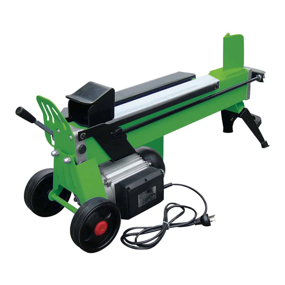
Page 1: Log Splitter
LOG SPLITTER FOR YOUR SAFETY READ AND UNDERSTAND THE ENTIRE MANUAL BEFORE OPERATING MACHINE MODEL NUMBER : 150-51-50255 Save This Manual for Future Reference... -
Page 2: Safety Warnings And Cautions
SAFETY WARNINGS & CAUTIONS SYMBOL AFFIXED TO THE SAFETY WARNINGS & INSTRUCTIONS MACHINE UNDERSTAND YOUR LOG SPLITTER Read and understand the owner’s manual and labels affixed to the log splitter. Learn its application and limitations as well as the specific potential hazards. -
Page 3: Extension Cords
EXTENSION CORDS Improper use of extension cords may cause inefficient operation of the log splitter which can result in overheating. Be sure the extension cord is no longer than 10m and its section is no less than 2.5mm to allow sufficient current flow to the motor. Avoid use of free and inadequately insulated connections. -
Page 4: Protect Your Hands
PROTECT YOUR HANDS Keep your hands away from splits and cracks which open in the log; They may close suddenly and crush or amputate your hands. Do not remove jammed logs with you hands. DON’T FORCE TOOL It will do a better and safer job at its design rate. Never try to split logs larger than those indicated in the specifications table. -
Page 5: Application Conditions
C and for installation at altitudes no more than 1000m above M.S.L. The surrounding humidity should less than 50% at 40 C. It can be stored or transported under ambient temperatures between -25 C and 55 SPECIFICATIONS Model Number 150-51-50255 Motor 230V~ 50Hz 1500W IP54 5 ~ 25cm Diameter... -
Page 6: Set Up And Preparation For Operation
SET UP AND PREPARATION FOR OPERATION 1. Bolt the Support Leg to the Log Splitter, lift the log splitter by the handles at both ends and place it on a 60 – 75cm high, stable, flat and level work surface. 2. -
Page 7: Wiring Diagram
15. Max Pressure Limiting Screw DO NOT ADJUST THE MAX PRESSURE LIMITING SCREW ! Max pressure was set before the log splitter ex work and the max pressure limiting screw is sealed with glue to ensure the log splitter works under pressure no more than 4 tons. -
Page 8: Log Splitter Operation
LOG SPLITTER OPERATION This log splitter is equipped with “ZHB” control system that requires to be operated by both hands of the user – Left hand controls the hydraulic control lever while right hand controls the pushbutton switch. The log splitter will freeze upon absence of either hand. Only after both hands release the controls, the log pusher starts to return backward to the starting position. -
Page 9: Freeing A Jammed Log
Break log in the direction of its growing grain. Do not place log across the log splitter for splitting. It may be dangerous and may seriously damage the machine. Do not attempt to split 2 pieces of logs at the same time. One of them may fly up and hit you. -
Page 10: Replacing Hydraulic Oil
REPLACING HYDRAULIC OIL Replace the Hydraulic oil in the log splitter after every 150 hours of use. Take following steps to replace it. Make sure all moving parts stops and the log splitter is unplugged. Unscrew Oil Drain Bolt with Dipstick to remove ... -
Page 11: Sharpening Wedge
SHARPENING WEDGE After using the log splitters for some time, sharpen the wedge of the log splitter using a fine-toothed file and smooth any burrs or crushed area along the cutting edge. TROUBLE SHOOTING PROBLEM PROBABLE CAUSE REMEDY SUGGESTED Overload Protection Device Contact a qualified Electrician for opening... - Page 13 Part# Name Specification Quautity Two-head bolt oil cylinder big spring aluminum cover for oil cylinder Ø55 1set gasket ring Ø5.3X1.8 bleed screw M6X16 combined pad oil ruler pad for cylinder cover 30X3.55 CK style combined ring piston rubber pad 23.6X3.55 ST style combined ring gasket ring ?...
- Page 14 wheel back support nut of non standard hydraulic button cover type nut plug screw M6X8 steel ball SØ6 spring Ø1.8X6.2 combined pad Ø8 screw M8X8 guard for handle washer aluminum block spring Ø0.8X7.8 combined pad plug screw split washer small spring Ø1.2X29 small shaft gasket ring...
- Page 15 gasket ring 10.6X1.8 gasket ring 55X3.1 plastic pad 1 main support pushing plate left guard hexagon bolt M6X12 worktable bolt M6X16 front support right support locknut inner hexagon screw M10X20 locknut plastic pad 2 motor 4X2.5 Head Oilseal fornt cover of motor boolt M8X35 footpad...
- Page 16 bolt M6X25 spring washer washer spindle sleeve without oil middle board straight pin Ø8X25 gasket ring 46.2X1.8 gear Steel Cable Baffle Ring Ø10 driven shaft gasket ring Ø10X2.65 steel ball SØ2.5 gear pump bolt M8X30 combined pad washer spring washer bolt M8X50...
Need help?
Do you have a question about the 150-51-50255 and is the answer not in the manual?
Questions and answers