
Summary of Contents for MODELSVIT USS PERMIT SSN- 594 CLASS
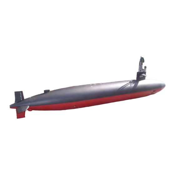
- Page 1 USS PERMIT SSN- 594 CLASS Model Submarine Hull Kit in 1:72 Scale Assembly Instruction Manual...
-
Page 2: Table Of Contents
Permit Manual rev-1 5/22/2008 Table of contents: 1. Introduction 14. Cutting Out Holes 2. Background Information 15. Stern Planes 3. Class Specifications 16. Rudders 4. Recommended Tools 17. Sail Assembly 5. Recommended RC Accessories And 18. Sail Planes Vendors 19. Circa 79 Towed Array Assembly 6. -
Page 3: Introduction
Permit Manual rev-1 5/22/2008 1. Introduction Thanks for purchasing your new model Permit class attack submarine! Your new highly-detailed model is intended not only to provide many hours of quality RC running time in freshwater ponds, lakes or pools, but is meant to be a fun and good learning experience while building it as well. - Page 4 Permit Manual rev-1 5/22/2008 unlikely to happen to any submarine after the loss. Although there were 14 boats altogether in the Permit class, very few of the boats, if any, were identical to each other. Some examples of this were: SSN-613 USS Flasher, SSN-614 USS Greenling, SSN-615 USS Gato all had 10’ longer hulls and a longer sail for added SUBSAFE machinery, SSN-621 USS Haddock had a long sail but regular Permit hull, SSN-596 Barb was the only ship of the class with “puffer fins”...
-
Page 5: Class Specifications
Permit Manual rev-1 5/22/2008 3. Class Specifications: • Displacement: Surfaced: 3,540 t., Submerged: 4,200 t. • Length: 278 feet 297 feet SSN-605 292 feet SSN-613-615 • Beam: 31’ 8” • Speed: Surfaced 15 knots, Submerged 28+ knots; • Operating Depth: 400' •... -
Page 6: Recommended Tools
Permit Manual rev-1 5/22/2008 4. Recommended tools This list is a compilation of “recommended” tools only. By no means are you expected to go out to the store and buy everything you see listed here. There are always different ways and different tools used to accomplish a task. -
Page 7: Recommended Materials
Permit Manual rev-1 5/22/2008 6. Recommended Materials and Consumables • • Pencils Air dry glazing putty (Nitro-Stan or • Evercoat) Dishwashing abrasive pads • • Polyester auto body filler (Evercoat Sharpie marker(s) with miracle sanding) • Masking tape • Popsicle sticks or tongue depressors •... -
Page 8: Marking Out Where Everything Goes
Permit Manual rev-1 5/22/2008 8. Marking Out Where Everything Goes A good idea before you start cutting and drilling is to mark out where everything goes. You can start by taking your Sharpie marker and drawing in all the scribed details in the plastic. Doing this makes everything easier to see and work with. - Page 9 Permit Manual rev-1 5/22/2008 • Repeat this procedure for the top hull half at your 3” line. Carefully run your razor saw along the line making a groove or “path” that will allow easier cutting, giving the blade a path to follow when doing your main cut. This is essential to getting a clean line with the least amount of material being removed.
-
Page 10: Registry Lips
Permit Manual rev-1 5/22/2008 10. Registry Lips This kit comes supplied with a bow, stern, port and starboard fiberglass registry lips that will help hold the two hull halves together tightly in conjunction with the provided carbon fiber spring clips. •... - Page 11 Permit Manual rev-1 5/22/2008 • Mark along the bottom of the lips along the length of the hull and then sand between them below that line and the hull edge with 100-grit sandpaper and then clean with lacquer thinner. • Mask off all the surfaces that are not to be glued on the lips.
-
Page 12: Registry Clips
Permit Manual rev-1 5/22/2008 • Disassemble the hull halves • Hacksaw some grooves and scour the surface of the provided 4-40 stainless nuts • Grease the two 4-40 by ¼” long machine screws provided with Vaseline • Tighten the nuts (on the insides of the bow and stern lips) through the lips to their screws and epoxy the nuts in place. -
Page 13: Drive Train
Permit Manual rev-1 5/22/2008 • Once cured, you can now fit the two hull halves together and check for fit 12. Drive Train Installation The drive train includes mounting the included forward bearing supporting bulkhead and an aft 3/16” Oilite bearing that supports the drive shaft and lubricate it as well. These are not your typical bearings as they sintered bronze bushing impregnated with oil, a far more “maintenance friendly”... - Page 14 Permit Manual rev-1 5/22/2008 • Slide an Oilite bearing flush with one end over the shaft and place the other end of the shaft through the back of the boat so that it slides through the 3/16” bearing that is cast into the bearing bulkhead •...
- Page 15 Permit Manual rev-1 5/22/2008 • Lay wax paper on the floor and suspend the hull upright over the paper so that the stern is pointing straight down. You can clamp or tape the boat in place if you’re able to, so that it doesn’t fall over. Use modeling clay around the base of the taper where it touches the ground to help seal in any epoxy that might try leaking.
-
Page 16: Hull Formers
Permit Manual rev-1 5/22/2008 13. Installing Hull Formers (WTC Saddles) Hull formers, or otherwise known as WTC saddles, pretty much do as their name implies. They are basically a bulkhead that adds strength and rigidity to the light fiberglass hull shell, and provide a way to mount your watertight container inside the boat in perfect axial orientation. - Page 17 Permit Manual rev-1 5/22/2008 • Cut the hull formers at the designated cut lines (It’s possible this might already be done). The bottom formers are designated by the little wart located on the side • Place the WTC with the nylon dog bone connector in place in both the drive shaft universal socket and the WTC universal socket.
- Page 18 Permit Manual rev-1 5/22/2008 • Take the WTC out and draw lines where you want your formers to go, around the whole half of the hull inside • Take the formers out and grind and scruff the area that the formers will be bonded to.
- Page 19 Permit Manual rev-1 5/22/2008 • To hold the WTC in place, there is no limit to the options that one can take. Some have used Velcro glued to the hull and had Velcro belts hold the WTC down. You can drill holes in the top of the bottom cradles, thread bolts in and run an elastic or small bungee hanging on the bolts cord across to the other side of the cradle.
- Page 20 Permit Manual rev-1 5/22/2008 14. Cutting Out Vent And Drainage Holes Holes need to be cut out on the hull to allow for air to escape out the top and water to flow in and out of the bottom for RC operation. This probably is the right time to do this, as there are no appendages to get in the way of turning your hull to proper position to cut the holes out.
-
Page 21: Stern Planes
Permit Manual rev-1 5/22/2008 15. Stern Planes It’s time now to start installing the fins, and we’ll start with the stern plane assemblies. The proper installation of these is critical for having everything line up cosmetically, and for proper function of the boat. The line where you glued the stern piece onto the bottom hull half is your middle reference point where the center of the stern planes should be mounted directly on. - Page 22 Permit Manual rev-1 5/22/2008 • Using some epoxy filled with adhesive filler (mixed to a peanut butter consistency), assemble the planes on the 1/8” shaft once again and glue into place. The key here is to use just enough adhesive to glue the parts on and fill all the voids.
- Page 23 Permit Manual rev-1 5/22/2008 • Hold the plane down with slight pressure and pull the sandpaper through at the same time. Repeat a couple of times with the sandpaper facing in, and then flip over for a couple of passes on the plane itself. The plane should be able to move completely without binding on the stabilizer SSN-594 CLASS Page 23 of 43...
-
Page 24: Rudders
Permit Manual rev-1 5/22/2008 16. Rudders Before you begin to actually install the rudders, a good idea would be to make an alignment jig out of clear plastic so you can ease the installation of the parts and ensure that they are perfectly perpendicular to the stern planes. •... - Page 25 Permit Manual rev-1 5/22/2008 • Put all the planes in place in their bearings and take a good look at how it all looks together set up. This will be the only convenient time you will have to be able to reposition the bosses if so needed. If you do, pry the bosses up with a flathead screwdriver and begin the alignment process over.
- Page 26 Permit Manual rev-1 5/22/2008 other hand drag the sail over the sandpaper removing material from whichever side needs it. It takes very little sanding to move the sail a few degrees one way or the other! • Tack the mounting assemblies in place with a little CA. The shorter, fatter one goes in the front, and the longer, sharper one is for the rear of the sail •...
- Page 27 Permit Manual rev-1 5/22/2008 • For the open version, file all the holes so that they accept the appropriate mast and periscope in a manner that provides easy install and removal and that the scopes are supported straight up and down. Note: Do not glue the scopes into place, as they have to be able to be removed Note: the following scope rack assembly is designed to align and hold the masts and scopes straight up and down and from side to side and should provide a loose fit that...
-
Page 28: Sail Planes
Permit Manual rev-1 5/22/2008 18. Installing the Sailplanes The sailplanes provide your boat with the ability to control its depth, just like on the real boat. You have the option to glue the sailplanes directly to the sail, but they have been designed to function, as they have brass collars and setscrews molded right into them for attaching to a rotating 1/8”... - Page 29 Permit Manual rev-1 5/22/2008 19. Circa ’79 Towed Array Fairing And Extraction Tube The circa ’79 add-on kit (ordered separate from the base kit) comes with a solid resin towed array fairing, it’s accompanying extraction tube and a GNATS sonar jammer hump, all of which have to adhered to the hull and are not represented on the Circa 1961 drawings that are provided with the kit.
- Page 30 Permit Manual rev-1 5/22/2008 • Remove the part and scour the surface where you marked and clean with lacquer thinner • Use filled epoxy to adhere the part in place and use masking tape to hold it in place while curing •...
- Page 31 Permit Manual rev-1 5/22/2008 • For installing the GNATS sonar jammer begin by finding the centerline on the top of the top hull half. This can be achieved by running a flexible straightedge between the middle of the aft escape hatch and the upper rudder mid-point •...
-
Page 32: Mechanical Linkages
Permit Manual rev-1 5/22/2008 20. Mechanical linkages This part can be a little tricky, but all one really needs is a steady hand and a good pair of needle nose pliers. I recommend fish hook removal pliers, as the nose on these are extra skinny and are designed to get a good grasp on things. - Page 33 Permit Manual rev-1 5/22/2008 • Turn the boat onto its side and slide the rudders into their respective bearings • Holding the rudder U-shaft link with your needle nose pliers, push a rudder shaft through the bearing and then through one of the u-shafts holes, repeat for the other rudder.
-
Page 34: Pre-Paint Preparation
Permit Manual rev-1 5/22/2008 • You can now install the sailplanes ensuring that they line up perfectly and have a small gap between them and the sail. You can even put a small stainless steel or Teflon (size #6) washer in between the planes and the sail to maintain that gap. You can now tighten their set screws when you are happy with the placement Note: All the planes should move freely without binding, as any hindrance in movement can cause overworking of motors causing excessive battery drainage and put undo strain... - Page 35 Permit Manual rev-1 5/22/2008 Note: A good idea is if you are not familiar with using any of these types of products, would be to practice using small amounts of them on a scrap piece of wood or plastic. This way you can become familiar with the application, curing and sanding properties of each product and not have to worry about wrecking anything on your model •...
-
Page 36: Paint
Permit Manual rev-1 5/22/2008 filler material takes too long to dry, adds more sanding, and could possibly crack with temperature changes • Wet sand with 400-grit sandpaper • Spot prime all the surfaces that had blemishes and let dry. (The high quality primers dry faster than the spray balm stuff) This will let you see if any blemishes remain or if more sanding is needed. -
Page 37: Detailing
Permit Manual rev-1 5/22/2008 23. Detailing Here is where you add those finishing touches that add so much to the look of your model. You can add stainless steel MBT vents and grating to the sail and hull using the provided photo-etched detail sheet. - Page 38 Permit Manual rev-1 5/22/2008 to make a jig like that shown below and use masking tape as a way to temporarily mark out their locations. • White metal pieces such as cleats and capstans should have their bonding surface roughed up with sandpaper, or ultimately if you want to paint the parts as well, given a short dip in Ferric Chloride (acquired at Radio Shack or The Source By Circuit City) to chemically create porosity in the surface to better accept glue or paint.
- Page 39 Permit Manual rev-1 5/22/2008 24. Trimming the Model Trimming your model is the process in which you add a combination of weight and buoyant material to it to achieve a scale waterline when your boat is surfaced and a very slight buoyant condition when in submerged mode. To achieve this, you must first acquire around 16 ounces of lead weight or more and some pink or blue closed cell foam.
- Page 40 Permit Manual rev-1 5/22/2008 attack periscope. Leave the rest of the holes open so that air trapped in the sail can be released when submerging. • Slide elastic bands on the outside of the hull over the bow, stern, and over where the ballast tank is •...
- Page 41 Permit Manual rev-1 5/22/2008 • Command a blow from the wtc from your radio and see where the water line ends up on the boat. If you are close to where the designed water line should be then your boat is good to go. If it is sitting too high in the water you will have to add neutrally buoyant material to the ballast tank to adjust for this and then go through the trimming procedure all over again.
-
Page 42: Credits
Permit Manual rev-1 5/22/2008 25. References and Credits • Plans by Greg Sharpe at www.deepseadesigns.net • Ideas, inspiration and support at: o www.subpirates.com www.subcommittee.com • Picture usage and facts from the horses’ mouths: www.uss-jack.org - webmaster: Robert Mitchell www.usspermit.com - webmaster: Dave Stoops www.navsource.org •... - Page 43 Permit Manual rev-1 5/22/2008 SSN-594 CLASS Page 43 of 43...
Need help?
Do you have a question about the USS PERMIT SSN- 594 CLASS and is the answer not in the manual?
Questions and answers