Table of Contents

Subscribe to Our Youtube Channel
Summary of Contents for Marthon AVR SE350
- Page 1 I n s t a l l a t i o n • O p e r a t i o n • M a i n t e n a n c e Voltage Regulator Marthon AVR SE350 hanada technology Co.,Ltd.
- Page 2 SE350 VOLTAGE REGULATOR INSTRUCTION MANUAL...
- Page 3 INTRODUCTION The SE350 voltage regulator is an encapsulated electronic voltage regulator that controls the output of a brushless AC generator by regulating the current into the exciter field. SPECIFICATION SE350 REGULATOR Sensing & Power Input 190-240 Vac Burden 500 VA Output Power- Continuous 73 Vdc at 3.5 Adc (255w) Output Power - Forcing(240 Vac Input Power)
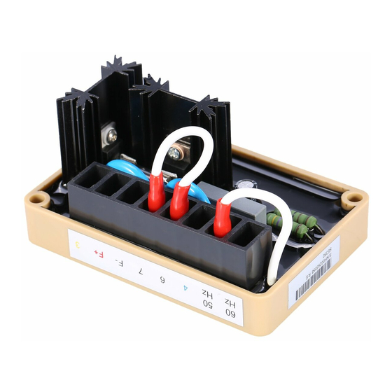
- Page 4 The SE350 voltage regulator can be mounted in any plane, following are mounting dimensions. FIGURE 1 FUSE A 4 Amp, 250 V, 5 X 20 mm fuse is supplied with the regulator (Part A-527066). It can be located on the rear face of the voltage regulator. EXCITER POWER CIRCUIT Connect the regulator wire F+ to the generator F+ or Fl field terminal.
- Page 5 FIGURE 2 VOLTAGE ADJUST The screwdriver adjustable potentiometer adjusts the generator output voltage. Adjustment clockwise increases the generator output voltage. When using a remote voltage adjust rheostat, remove the jumper wire across terminals 6 and 7 and install a 2000 ohm 1/2 watt (minimum) rheostat. This will give ±10% voltage variation from the nominal.
- Page 6 PRELIMINARY SET-UP Ensure the voltage regulator is correctly connected to the generator. Refer to the specific connection diagram supplied with the generator. Set the regulator voltage adjust to full counter-clockwise (minimum voltage level). Set the remote voltage adjust (if used) to the center position. Set the stability control full clockwise (maximum stability level).
- Page 7 TROUBLESHOOTING Symptom Cause Action Residual Voltage -No Residual voltage at regulator power Check wiring diagram for Output input wires 3 & 4 below 10 V ac. proper connections. Flash generator field. Refer to field flashing section in generator manual. Acceleration time to rated speed too Reduce acceleration time.
Need help?
Do you have a question about the AVR SE350 and is the answer not in the manual?
Questions and answers