
Summary of Contents for Misonix SONICATOR 3000
- Page 1 SONICATOR ® 3000 ULTRASONIC LIQUID PROCESSOR OPERATION MANUAL M I S O N I X MISONIX INCORPORATED 1938 New Highway, Farmingdale, NY 11735 U.S.A. Telephone: 631-694-9555 Fax: 631-694-9412 Toll Free: 1-800-645-9846 w w w.misonix.com...
-
Page 2: Table Of Contents
TABLE OF CONTENTS Safety - Warnings and Precautions Getting Started Inspection Power Requirements Placement of Equipment Specifications for S3000 Description of Major Components Generator (Power Supply) Process Control Features of Model S3000 Convertor (Transducer) Horn (Probe) Replacement Flat Tips Description of Controls and Connectors Front Panel Description Rear panel Description Preparation for Use... - Page 3 Tip Care 10-2 Applications 11-1 Principle of Ultrasonics 11-1 Processing Tissue 11-1 Processing Difficult Cells 11-2 Techniques 12-1 Probe Depth 12-1 Foaming and Aerosoling 12-1 Viscosity Limitations 12-1 Keeping Samples Cool 12-1 Free Radical Formation 12-1 Warranty 13-1 Return of Equipment 14-1 Literature Request 15-1...
-
Page 4: Safety - Warnings And Precautions
Operation Manual Getting Started SAFETY - WARNINGS AND PRECAUTIONS Read ALL Instructions Before Installing or Using Equipment Your new Ultrasonic Liquid Processor has been designed, built and tested to assure maximum operator safety. However, no design can completely protect against improper use that may lead to bodily injury and/or property damage. -
Page 5: Getting Started
Unpack the unit from its shipping carton and check the contents against the packing list. Before disposing of the packing material, check it carefully for small items. Report any missing components to Misonix immediately. Visually inspect all external controls, indicators and surfaces to detect any damage in transit. If damage has occurred, contact your carrier within 48 hours of delivery date. -
Page 6: Specifications For S3000
** In a Vacuum area, additional cooling provisions may be needed. ACCESSORIES Use only accessories and probes listed in the Misonix catalog as suitable for operation with this equipment. Do NOT attempt to fabricate ultrasonic tooling or accessories as the use of improper equipment can damage the Sonicator®... -
Page 7: Description Of Major Components
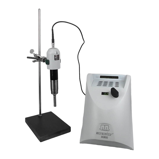
Operation Manual Description of Major Components DESCRIPTION OF MAJOR COMPONENTS Generator Includes all operating controls and indicators, detachable three-wire grounded line cord, fuse, external power control jack and high frequency cable connector. Process Control Feature of the Sonicator® 3000 • Microprocessor Controller - allows precise control of output amplitude, elapsed processing time, and cyclical rates during power pulsing. - Page 8 Operation Manual Description of Major Components 1/16" thick sapphire disk bonded to the tip of a solid horn. Replaceable Flat Tips Tapped horns have replaceable flat tips, at the radiating surface attached to the end of the horn. The flat tips will erode with use and are replaceable. Tip size matches horn diameter.
- Page 9 Operation Manual Function of Controls and Indicators FUNCTION OF CONTROLS AND INDICATORS 1 - LCD Message Display 2 - Keypad 3 - Amplitude Setting Display 4 - Amplitude Setting Knob...
-
Page 10: Rear Panel Description
Operation Manual Function of Controls and Indicators S3000 REAR PANEL DESCRIPTION... -
Page 11: Preparation For Use
Operation Manual S3000 Operating Instructions PREPARATION FOR USE To safeguard the fuse against failure, always switch the power supply off before connecting or disconnecting the power cord. Check to make sure that the Power Switch on the generator is turned OFF. Connect the Power Cord to the receptacle on the rear of the generator and plug it into a grounded power outlet. -
Page 12: Convertor Mounting Diagram
Operation Manual S3000 Operating Instructions CONVERTOR MOUNTING DIAGRAM Incorrect convertor clamping Correct convertor clamping. method. -
Page 13: Attachment And Removal Of Horns And Tips
STOP processing immediately. Turn off the generator and check the tightness of the horn to the convertor, and the tip or probe to the horn if applicable. If the loud noise persists, contact MISONIX for assistance. See diagram on next page... - Page 14 Operation Manual S3000 Operating Instructions ATTACHMENT AND REMOVAL OF TIPS AND HORNS...
-
Page 15: S3000 Operating Instructions
Operation Manual S3000 OPERATING INSTRUCTIONS S3000 OPERATING INSTRUCTIONS Review of Keys Action START Starts or Stops output in all modes of operation. Resets timer in STOP timed mode. PROG Initiates Timer and PULSAR entry program and displays entries on DATA the LCD screen during run. - Page 16 OPERATION AND PROGRAMMING INFORMATION Power-Up At power-up, the following message will scroll onto the display: SONICATOR 3000 MISONIX INCORPORATED The above screen will stop scrolling, then, after a short time, the MicroTip question will appear. (At any time during the scrolling message, pressing any key will immediately display the MicroTip question).
- Page 17 Operation Manual S3000 OPERATING INSTRUCTIONS Programming Mode When the Programming Mode is selected, the following five screens will cycle in succession, changing at three-second intervals: 00:00:00 Program 1 Shows currently-programmed timing information for 00:00.0 00:00.0 Program 1 (Program 1 is the default). No Temperature This screen may be different depending on Control Selected...
- Page 18 Operation Manual S3000 OPERATING INSTRUCTIONS 1) Selecting a Programmed Memory Setup There are nine possible program memories that store programmed setup information, and maintain those programmed parameters even after turning off the unit. Any one of those nine memory setups (Program numbers) can be accessed by pressing the associated numeric key, [1] to [9], on the keypad (i.e.: pressing the [5] key will bring up the programmed settings for Program 5).
- Page 19 Operation Manual S3000 OPERATING INSTRUCTIONS Pulse-ON Time Programming After entering the desired Process Time, the next screen prompts for the Pulse-ON time, with the top line alternating at three-second intervals: Set Pulse “ON” Time Then Press ENTER 00:00.0 (min:sec.tenths) 00:00.0 (min:sec.tenths) If processing continuously, (no pulsing), enter 00:00.0 for the Pulse-ON time and press ENTER.
- Page 20 Operation Manual S3000 OPERATING INSTRUCTIONS Programming Temperature Control If YES is pressed for the Temperature Monitoring question, the next question asked is: Temperature Control (Y/N)? Answer YES if a maximum shutdown temperature or external control temperature will be used. Answer NO if the temperature will be shown on the display while processing, but with no temperature control.
-
Page 21: Accessories
Operation Manual Accessories ACCESSORIES CUP HORN Installation Install and hand tighten the cup horn onto the convertor. Tighten the horn with the pin spanner wrenches. Support the convertor and cup horn in the Sonabox Acoustic Enclosure or in a lab stand using two clamps on the convertor case only. - Page 22 The cup is made of acrylic plastic and should be cleaned periodically with a mild detergent, not with abrasives or solvents. The horn is a tuned resonant body of titanium alloy. Do not attempt to resurface the horn if it shows erosion after extended use. Contact Misonix if...
- Page 23 Operation Manual Accessories problems occur. ™ FLOCELL Flocells™ are used for the continuous processing of large volumes of sample material. The liquid is pumped into the Flocell™ through a carefully designed opening so that all of the sample passes through the cavitation field and receives maximum, uniform sonication. The annulus and orifice sizes are variable to accommodate differing viscosity and flow rate.
- Page 24 Operation Manual Accessories Stainless Steel Model (Part # 800C) Clean cell and all metallic parts with appropriate solution. Install the #228 size O-ring on to the horn. Attach horn to the convertor and tighten using pin spanner wrenches as described in sections 6-3 and 6-4.
-
Page 25: Microtip Tm
Operation Manual Accessories MICROTIP Part Numbers: (418, 419, 419A, 419B) MICROTIPS attach directly to the end of the ½” diameter tapped horn in place of the flat tip. The MICROTIP Probes are tapered down to a narrow point and serve as a third stage of acoustic amplification. -
Page 26: Extender Tip
Cracked, broken or eroded discs can be removed from used horns and replaced at the factory. Contact MISONIX or local representative for current replacement information. Be sure to store sapphire tipped horns in a safe place and well protected from impact. -
Page 27: Sonabox Tm
Operation Manual Accessories SONABOX Before unpacking or assembling, please READ INSTRUCTIONS carefully. See page 8-8 for diagram. Unpack by grasping the Enclosure body to lift from carton. DO NOT lift by latch assembly (door handle). Open SONABOX by lifting latch handle to the horizontal position and turning handle 90 in either direction. - Page 28 Operation Manual Accessories Unpack by grabbing the enclosure body not the door handle. Open the door by turning the latch in either direction. Standard Horn or Microtip assembly: see figure 1A Remove the four screws from convertor next, invert neck with cylindrical sleeve outward and reinstall screws.
-
Page 29: Troubleshooting
Check tightness of horns and/or tips. Remove tips and clean threads and mating surfaces if necessary. Check horn for cracks or excessive tip erosion. If all above fails to rectify problem, consult Misonix, Inc. Customer Service Department. Troubleshooting Guide SYMPTOM... -
Page 30: Maintenance
Make certain the cable always has slack and is never tensioned. If necessary, move the generator or convertor assembly closer to one another to accomplish this. If this is not possible, contact Misonix to obtain a longer cable. ®... -
Page 31: Tip Care
Operation Manual Maintenance Tip Care The probe tip may be sterilized either by immersing in boiling water, autoclaving, or in a detergent bactericide and a disinfectant. DO NOT AUTOCLAVE OR IMMERSE CONVERTOR AT ANY TIME. Before each procedure place the probe tip in water or alcohol and turn the power on for a few seconds to remove residue. -
Page 32: Applications
Operation Manual Applications APPLICATIONS Principles of Ultrasonics The generator (power supply) converts conventional 50/60 Hz AC line power to 20kHz electrical energy that is fed to the convertor where it is transformed into mechanical vibration. The heart of the convertor is a piezoelectric crystal stack which, when subjected to an alternating voltage, expands and contracts. -
Page 33: Processing Difficult Cells
Operation Manual Applications Processing Difficult Cells When processing difficult cells, the use of enzymes should be considered. Glusulase can be used with yeast, lysostaphin can be used with staphylococcus, collagenase can be used with skin and cartilage, and trypsin hyaluronidase can be used with liver and kidney. Glass beads in the 10 to 50 micron size range can also be added to the liquid to expedite processing. -
Page 34: Techniques
Operation Manual Techniques TECHNIQUES Probe Depth Immerse the probe tip not less than 1 to 1-1/2 times the tip diameters into the solution, without touching the bottom. This depth rate applies to the " horn; immersion depth can be less for larger horns and may have to be more for smaller probes used at higher intensity. -
Page 35: Warranty
The obligation of MISONIX Incorporated under this guarantee will be to make any repair at its plant in Farmingdale, New York, or at any of its designated service centers, without charge, including parts and labor, but not including shipping charges, necessitated by any defect in workmanship or material. -
Page 36: Return Of Equipment
IMPORTANT NOTICE BY RETURNING ANY MATERIAL TO MISONIX INC., THE CUSTOMER OR THE CUSTOMER'S AGENT THUS CERTIFIES THAT ANY AND ALL MATERIALS SO RETURNED ARE, OR HAVE BEEN RENDERED, FREE OF ANY HAZARDOUS OR NOXIOUS AND/OR INFECTIOUS MATTER OR RADIOACTIVE CONTAMINATION AND ARE SAFE FOR HANDLING UNDER NORMAL REPAIR SHOP CONDITIONS. -
Page 37: Literature Request
Operation Manual Literature Request LITERATURE REQUEST Available from Misonix is descriptive material on ultrasonic liquid processing. To order, place a check next to the title you wish to receive. (Quantity limit is one copy per title) PUBLISHED PAPERS: RPT-I "Probe Ultrasonics: Increased Productivity and Accelerated Reactions in the Modern Laboratory", American Laboratory News... -
Page 38: Technical Notes
Operation Manual Literature Request TECHNICAL NOTES: TN-1 Amplitude Measurement TN-2 Extenders and Sapphire Tips TN-3 Extending Control Range TN-4 Microtips TN-5 Half-Wave Length Extender Tips TN-6 Flow Cells TN-7 Development of Protocols TECHNICAL BULLETINS: TB-1 Ultrasound, Hearing and Health TB-3 Sifting Solids TB-4 Pulsed Sonication...
Need help?
Do you have a question about the SONICATOR 3000 and is the answer not in the manual?
Questions and answers