Table of Contents
Advertisement
Advertisement
Table of Contents

Summary of Contents for Amada MM-315B
- Page 1 Original instructions WELD TESTER MM-315B OPERATION MANUAL S09M0834E-15...
-
Page 2: Table Of Contents
MM-315B Thank you for your purchase of the Amada Miyachi Weld Tester MM-315B. Please read this manual carefully to ensure correct use. Keep the manual handy after reading for future reference. Contents 1. Special Notes.....................1-1 (1) Safety Precautions ......................1-1 (2) Handling Precautions ......................1-4 2. -
Page 3: Special Notes
MM-315B 1. Special Notes (1) Safety Precautions Prior to use, read these “Safety Precautions” carefully to gain a full understanding of the proper method of use. The precautions listed here are designed to ensure safe use and proactively prevent ■... - Page 4 Continuous operation after occurrence of a trouble such as burning smell, abnormal sound, abnormal heat, smoke, etc. can cause electric shock and fire. If such a trouble occurs, immediately consult Amada Miyachi Co., Ltd. or your distributor. Persons with pacemakers must stay clear of the welding machine.
- Page 5 MM-315B CAUTION Do not expose to water or other liquid. Exposing electrical components to water or other liquid may result in electric shock or short-circuiting. Keep combustible matter away from the device. Spatter may ignite combustible matter. If it is impossible to remove all combustible matter, cover it with non-combustible material.
-
Page 6: Handling Precautions
MM-315B (2) Handling Precautions Avoid the following locations when installing the device: ■ • Humid location (humidity of above 90%) • Extremely hot (above 40°C) or cold (below 0°C) locations • Near a high noise source • Location where chemical substances, etc. are handled •... - Page 7 ■ Do not short-circuit the connector of the charger using a screwdriver, etc. ■ Do not use the accessory charger for any unit other than the MM-315B. ■ ■ Remove the charger from the outlet when it is not in use.
- Page 8 MM-315B Even if the unit is not used for an extended period, charge it once every six months. ■ Do not use disposable alkaline batteries. ■ 1. Special Notes...
-
Page 9: Features
MM-315B 2. Features The MM-315B Weld Tester is a handheld instrument for measuring weld current. • Battery-driven type. Can be used anywhere freely. • Small and light design for ease of use. • Current, cycle and conduction degrees can be measured by connecting a toroidal coil (sold separately). -
Page 10: Packing List
1030606 Operation manual M0834E 1006873 *1 The MM-315B-00-05 does not come with a charger. Use a charger with the following specifications. Output: 7 V±10%, 100 mA minimum Polarity: Negative Center *2 The Japanese panel seal is for adding Japanese signage on the panel display. -
Page 11: Names And Functions Of Parts Of The Weld Tester
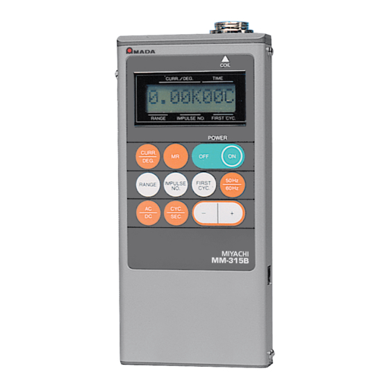
MM-315B 4. Names and Functions of Parts of the Weld Tester Toroidal-coil connector Connecting the toroidal coil (optional) LCD display Displays measured values or measurement schedules Buttons For setting measurement schedules Charger connector Connecting the charger to charge the built-in battery... -
Page 12: Measurement
Measure the weld current, using this instrument. (1) Setting the Toroidal Coil Mount the coil on the welder as shown below, and connect the cord to the connector of the MM-315B. Toroidal coil Place the center of the coil on the secondary conductor of the welder. -
Page 13: Supplying Power
MM-315B (2) Supplying Power Press the button. The measurement conditions are displayed for 0.7 seconds, and then the unit buttons to the initial display. The above display shows the unit set at 50 Hz AC. When it is set to 60 Hz DC, the display shows the following: <Initial display>... -
Page 14: Checking Measurement Setting
MM-315B (3) Checking Measurement Setting Measurement setting can be checked as follows. Press the The following display appears: button. RANGE IMPULSE NO. FIRST CYC. RANGE FIRST CYCLE --- First cycle to be measured. 1-99 cycles IMPULSE NO.--- Number of impulses to be measured. -
Page 15: Measurement Settings
MM-315B (4) Measurement Settings Measurement values can be set as follows. To set the measurement values, use the , and buttons (white) to select each mode. Use the buttons to set data. a. Range Setting The cursor is in the Lo range, at Chapter 4 (3), indicating that this mode can be set. -
Page 16: Impulse No. Setting
MM-315B b. Impulse No. Setting To set the Impulse No. to 1, press Press RANGE IMPULSE NO. FIRST CYC. Cursor moves to IMPULSE NO. Next, press the button. Press The Impulse No. becomes 1. The Impulse No. is set to 1. Hold down the button until the figure reaches 9. - Page 17 MM-315B NOTE1. Impulse No. Setting and Display When the Impulse No. is 0 When the Impulse No. is 0, the display will disappear to signal the start of the welding, and the Checker monitors all impulses. For example, suppose the following settings were used to monitor the weld shown below.
- Page 18 MM-315B When the Impulse No. is 1-9 The display shows the information only for the number that has been set when the Impulse No. is 1 to 9. For example, when the Imp. No. is set to 2 and the weld pattern is the same as Imp. No. 0, the following is displayed: Setting Impulse No.
-
Page 19: Setting Of The First Cycle
MM-315B c. Setting of the First Cycle Now press the button. Press The cursor moves to FIRST CYC. Press and set the First Cycle to 3. Press ↓ ↓ The First Cycle is set to the 3rd cycle. To measure weld the current, press the button to show the initial display. -
Page 20: Setting Of The Last Cycle
MM-315B d. Setting of the Last Cycle Press the button. Press The cursor moves to FIRST CYC. Next, hold down the button for three seconds. The display shows the following for two seconds and returns. Hold down this button for three seconds to switch between LAST OFF and LAST ON. -
Page 21: Checking Conduction Degrees
MM-315B (5) Checking Conduction Degrees After the weld current is measured, press while the current value is displayed. The conduction degrees can be checked. Press The Current and Cycles are shown. ° The conduction degrees are shown. Press again; the current and cycle values are shown. The current and conduction degrees are measured at the same time. -
Page 22: Current Measurement Of Frequency-Inverter Welders
MM-315B (6) Current Measurement of Frequency-Inverter Welders Current measurement of frequency-inverter welders is described here. First, press the button. Press The present setting is shown. Press to enter DC mode. Press Next, press the CYC./SEC. button to show the time-display SEC. - Page 23 MM-315B When the time shows SEC (seconds), the weld time is divided into 10-ms blocks from the start of the weld, and the number in FIRST CYC shows at which block the measurement begins as shown in the figure below.
-
Page 24: All Impulse Memory
MM-315B (7) All Impulse Memory Storing data: The MM-315B is able to store up to 9 pulsations with more than 1 cool cycle in the memory. Weld pattern Impulse 1 Impulse 2 Impulse 3 The following table shows the weld pattern:... - Page 25 MM-315B Confirmation of All Impulse Memory After the weld is performed using the previous weld schedule, press the button. Press Memory M is fixed. Current value Impulse No. The Impulse No. 1 current value is shown. To check the time, press again.
- Page 26 MM-315B Search for the spot to be displayed using the , and buttons. Select display display Conductio Current Time n degrees Imp. No. Set the Impulse No. using the buttons. Press the button to measure the current. 5. Measurement 5-15...
-
Page 27: Display In Unit Of Half Cycle
MM-315B (8) Display in Unit of Half Cycle A half-cycle weld is indicated by adding a decimal point to the left of the cycle symbol C. The point indicates 0.5 cycles, such as when a 12.5-cycle weld is performed, the display will be as follows: The decimal point indicates 0.5 cycles. -
Page 28: Button And Functions
MM-315B 6. Button and Functions ← → → 5. Button and Functions... - Page 29 MM-315B 5. Button and Functions...
- Page 30 MM-315B 5. Button and Functions...
-
Page 31: Specifications
When there is no button operation or no current measurement is performed for Power Off seven minutes. * The MM-315B-00-05 does not come with a charger. Use a charger with the following specifications. Output: 7 V±10%, 100 mA minimum Polarity: Negative Center... -
Page 32: Appearance
MM-315B 8. Appearance Unit: mm 8. Appearance... -
Page 33: Charging The Battery
MM-315B 9. Charging the Battery (1) Connecting the Unit and Charger This tester is designed specifically for use with nickel-hydrogen batteries. Recharging is performed by the charger. Connecting the charger AC outlet charger Plug Plug connector Recharge connector MM-315B Connect the plug to the recharge connector of the unit, and plug the charger into an outlet. -
Page 34: Service Life Of The Nickel-Hydrogen Batteries
MM-315B (4) Service Life of the Nickel-Hydrogen Batteries 1) Cycle life of charge/discharge More than 500 charges/discharges are possible with proper use. If the length of use becomes very short, even when the batteries have been charged properly, it may be necessary to change the batteries. -
Page 35: Calibration
MM-315B 10. Calibration To maintain the performance of the MM-315B, it is necessary to calibrate it periodically. The calibration is carried out at our factory. Send us your toroidal coil along with the MM-315B for calibration. As the conditions of degradation for the MM-315B differ depending on the operation environment, it is necessary to calibrate the toroidal coil and the MM-315B together.
Need help?
Do you have a question about the MM-315B and is the answer not in the manual?
Questions and answers