Table of Contents
Advertisement
Quick Links
LED
BRIGHT33™
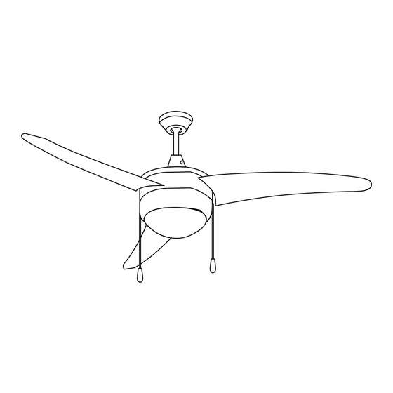
CONTEMPORARY 50"
LE D L IG HT IN G
3 BLADE CEILING FAN
Brushed Nickel Finish
INSTALLATION INSTRUCTIONS
Thank you for purchasing this
B33CF17W30BN
Integrated LED Ceiling Fan!
Please read carefully before installing ceiling fan.
Save these instructions, as you
may need them at a later date.
Toll Free: 1-800-316-2532
www.bright33.com
Please follow the following steps for installation.
Advertisement
Table of Contents

Summary of Contents for Bright33 B33CF17W30BN
- Page 1 LE D L IG HT IN G 3 BLADE CEILING FAN Brushed Nickel Finish INSTALLATION INSTRUCTIONS Thank you for purchasing this B33CF17W30BN Integrated LED Ceiling Fan! Please read carefully before installing ceiling fan. Save these instructions, as you may need them at a later date.
-
Page 2: Safety Instructions
SAFETY INSTRUCTIONS: GENERAL: All electrical connections must be in Turn power off before installation, inspection, or removal. Use all necessary precautions while performing accordance with local and National Electrical Code this procedure. (N.E.C.) standards. If you are unfamiliar with proper electrical wiring connections, contact and obtain Consult a qualified electrician to ensure correct branch circuit conductor. -
Page 3: Unpacking Instructions
UNPACKING INSTRUCTIONS: Remove contents from box. Ensure that no parts are missing. Reference the illustrations included with this instruction manual. 1. (2X) MOUNTING BRACKET 8. HARDWARE BAG INCLUDING THE FOLLOWING: 2. (1X) DOWNROD/BALL ASSEMBLY a. (2X) WOOD SCREW 3. (1X) CEILING CANOPY a. -
Page 4: Hanging Your Fan
HANGING YOUR FAN: Figure 1 SHUT OFF MAIN ELECTRICAL SUPPLY FROM THE MAIN FUSE BOX/CIRCUIT BREAKER! INSTALLING THE MOUNTING BRACKET & HOOK (FIGURES 1 & 2) THE CEILING FAN MUST BE INSTALLED IN A LOCATION WITH A MINIMUM OF 300MM (11.8 IN) SPACING FROM THE TIP OF THE BLADE TO THE NEAREST OBJECT OR WALL Insert the SECURITY HOOK through a hole in the OUTLET BOX that allows access to the ceiling joist, and screw securely into joist. - Page 5 Figure 3 DOWNROD/BALL ASSEMBLY (FIGURE 3) Take the DOWNROD BALL off from the DOWNROD by loosening the GROUND WIRE SCREW, and then Downrod Ball remove the bolt (DOWNROD PIN). DOWNROD/BALL ASSEMBLY (FIGURE 3) CONT. Route the SAFETY CABLE, through the same location as where the WHITE & BLACK WIRES exit the DOWNROD, and then screw the DOWNROD into the COLLAR COVER located above the motor housing.
- Page 6 Figure 6 ATTACHING THE FAN BLADES (FIGURES 4 & 5) CONT. Secure the BLADES with the 3 BLADE SCREWS, and ensure that the 3 BLADE SCREWS are evenly tightened. Do not over tighten the screws as this can damage the blades. Repeat this process for all blades.
-
Page 7: Wall Control Installation
WIRING: Figure 9 Carefully tuck all wiring back into the OUTLET BOX. Make sure wires are clear of the hemisphere and downrod when positioned on the MOUNTING BRACKET. WALL CONTROL INSTALLATION: ELECTRICAL CONNECTIONS (FOR OPTIONAL WALL CONTROL) Follow this wiring diagram. Wall control sold separately, choose ON/OFF light control only. - Page 8 Figure 10 GENERAL INFORMATION (FOR OPTIONAL REMOTE CONTROL) Remote control sold separately, choose ON/OFF light control only. After completing the electrical connection, cover the MOUNTING BRACKET with the CANOPY. Ensure that all electrical wiring is carefully tucked inside the canopy. Secure the CANOPY to the HANGER BRACKET using the SCREWS provided.
-
Page 9: Troubleshooting
OPERATION INSTRUCTIONS: Figure 12 Connect the WOOD TASSELS to the two pull chains located in the LIGHT KIT. One is for the FAN, and the other is for the LIGHT. Turn on power and check the operation of your fan. 3-SPEED PULL CHAIN: 1st Pull = High Speed, 2nd pull = Medium Speed, 3rd pull = Low Speed, 4th pull = OFF To turn the LIGHT KIT “ON”... -
Page 10: Cleaning And Maintenance
5-YEAR LIMITED WARRANTY: CAUTION: Ensure fixture temperature is cool enough to touch. DO NOT clean or perform maintenance while fixture LIMITED WARRANTY: Bright33™ Ceiling Fans are warranted to is energized. be free and clear of defects in materials and workmanship for a •...
Need help?
Do you have a question about the B33CF17W30BN and is the answer not in the manual?
Questions and answers