Samsung ME21F707MJT Service Manual
Hide thumbs
Also See for ME21F707MJT:
- User manual (52 pages) ,
- User manual (52 pages) ,
- User manual (28 pages)

Related Manuals for Samsung ME21F707MJT


Summary of Contents for Samsung ME21F707MJT
- Page 1 BASIC : SMH2117S MODEL: ME21F707MJT MODEL CODE: ME21F707MJT/AA 1. Precaution 3. Disassembly and Reassembly 4. Alignment and Adjustments 5. Troubleshooting 6. PCB Diagrams 7. Wiring Diagrams...
-
Page 2: Table Of Contents
7-1 Wiring Diagrams (ME21F707MJT/AA) ........ -
Page 3: Precaution
1. Precaution... -
Page 4: Safety Precautions
1. Precaution Follow these special safety precautions. Although the microwave oven is completely safe during ordinary use, repair work can be extremely hazardous due to possible exposure to microwave radiation, as well as potentially lethal high voltages and currents. 1-1 Safety precautions ( All repairs should be done in accordance with the 13. -
Page 5: Special High Voltage Precautions
1. Precaution 1-2 Special High Voltage Precautions High Voltage Warning Do not attempt to measure any of magnetron. High voltage is present during any cook cycle. Before touching any components or wiring, always unplug the oven and discharge the high voltage capacitor (See Figure 1-1) The high-voltage capacitor remains charged about 30 seconds after disconnection. -
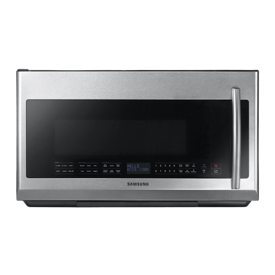
Page 6: Features
2-1 Features - Professional Design Samsung New OTR with Stainless Steel, it has professional look and the design matches great with other kitchen - Stirrer and Turntable Continually rotates food to ensure even cooking. - Instant Cook Instant On Controls - Allow quick, one touch cooking and reheating. - Page 7 (Cont.) BASIC MODEL NEW MODEL Items SMH2117S/XAA ME21F707MJT/AA SMH2117S/XAC ME21F707MJT/AC 1. Popcorn 2. Potato 3. Pizza Sensor Cook Mode 4. Cook 5. Reheat 6. Veggies 1. Kids Meals 2. Snacks 3. Soften Melt YES(3) YES(4) Auto Cook Mode 4. 1 Pound Defrost 5.
-
Page 8: Accessory
2-3 Accessory Item Description Code No. Q’ty Glass tray DE74-20002D Roller guide ring DE92-90189V Top Template DE68-03843A Wall template DE68-03142B Installation DE68-04108A instructions Use and Care Guide DE68-03970A Hardware-kit DE92-90505N FILTER AIR DE63-00196A (INSTALLED) DE63-30016D Shelf DE75-00083A Exhaust adaptor DE92-90242D... -
Page 9: Disassembly And Reassembly
3. Disassembly and Reassembly 3. Disassembly and Reassembly MAGNETRON, MOTOR ASSEMBLY, VENT BLOWER AND HIGH VOLTAGE TRANSFORMER Oven must be removed from wall. REMOVING OVEN FROM WALL (2 PEOPLE REQUIRED) Disconnect the power cord from the outlet. The oven is hooked on the metal tabs of the wall mounting plate that is secured to the wall. -
Page 10: Replacement Of High Voltage Transformer
3. Disassembly and Reassembly 3-1 Replacement of High Voltage Transformer Parts Explaination Photo Explaination Disconnect oven power. Remove Grille. Grille 1) Remove 2 screws 2) Slide the Grille to the left, then pull it straght out. Remove Panel Outer by Panel Outer pulling it to the rear of the set. - Page 11 3. Disassembly and Reassembly 3-1 Replacement of High Voltage Transformer Parts Explaination Photo Explaination Discharge the High voltage capacitor. High voltage capacitor Disconnect all the leads. Remove Base Bottom Base bottom. HV Trans Take out the HV Trans.
-
Page 12: Replacement Of Magnetron
3. Disassembly and Reassembly 3-2 Replacement of Magnetron Parts Explaination Photo Explaination Remove the magnetron including the shield case, permanent magnet, choke coils and capacitors (all of which are contained in one assembly). Disconnect all lead wires from the magnetron. Magnetron Remove nuts (2) securing the magnetron to the wave guide. -
Page 13: Replacement Of Fan Motor
3. Disassembly and Reassembly 3-3 Replacement of Fan Motor Parts Explaination Photo Explaination Remove Grille and Panel Outer. Disconnect all lead wires from Fan Motor and High Voltage Transformer. Put out Assy Fan Motor. Fan Motor Remove Fan Blade. Remove screws (2) securing Fan Motor. Replace Fan Motor to new one. -
Page 14: Replacement Of Door Assembly
3. Disassembly and Reassembly 3-4 Replacement of Door Assembly Parts Disassembly Photo Explaination Disconnect the lead wire. Removal of Remove Door pin. Door Pin Door Assembly Open the Assembly Door by degree 90º Seperate lifting Assembly Door from Set. 90º Removal of “A”... - Page 15 3. Disassembly and Reassembly 3-4 Replacement of Door Assembly Parts Disassembly Photo Explaination Removal of Remove 2 screws, then handle is detached from Handle Door “A”. Remove 4 screw securing Door “E” to Door “A”. Removal of insert and bend a thin metal plate between Door Door “E”...
-
Page 16: Replacement Of Fuse
3. Disassembly and Reassembly 3-5 Replacement of Fuse Parts Explaination Photo Explaination Disconnect power and remove grille. Replace the fuse. When 20A fuse blows out by the operation of interlock monitor switch failure, replace the primary interlock switch, secondary Fuse interlock switch, door sensing switch, interlock monitor switch and power relay. -
Page 17: Removal Of Stirrer
3. Disassembly and Reassembly 3-7 Removal of Stirrer Parts Explaination Photo Explaination CLIP COVER STIRRER The stirrer is located on the upper side of the cavity. The oven uses a side feed wave guide. Disconnect power and open the door. Stirrer Remove the clip and turn the stirrer cover left. -
Page 18: Replacement Of Control Circuit Board (Main Pba)
3. Disassembly and Reassembly 3-8 Replacement of Control Circuit Board (MAIN PBA) 3-8-1 MAIN PBA Parts Explaination Photo Explaination Disconnect power and remove grille. Be sure to ground any static electric charge in your body and never touch the control circuit. Removal of Control Box Remove a screw securing the control box... -
Page 19: Sub Module
3. Disassembly and Reassembly 3-8 Replacement of Control Circuit Board 3-8-2 SUB Module Parts Explaination Photo Explaination Remove the Door-E(14Page) Remove screws (2) securing the cover base. Lift up the cover base from the Ass’y door-A. Pull the lever end of the plastic fastener and remove the Flexible Printed Circuit(FPC) of Remove screws (3) securing the control circuit board. -
Page 20: Replacement Of Cooktop Lamp
Turn the power back on at the main power supply. NOTE1: To purchase a new LED lamp board, visit an authorized service center or call 1-800-Samsung (1-800-726-7864). NOTE2: The current of Normal LED lamp is 85mA ~ 150mA (in DC12V). -
Page 21: Replacement Of Oven Light
3. Disassembly and Reassembly 3-10 Replacement of Oven Light Parts Explaination Photo Explaination Remove the Grille Remove the COVER LAMP by removing the screw and put up the Oven Light lever. Replace the bulb with a 50 watt halogen bulb. -
Page 22: Alignment And Adjustments
3. Before touching any oven components or wiring, always unplug the oven from its power source and discharge the high voltage capacitor. 4-1 High Voltage Transformer Remove connectors from the transformer terminals and check continuity. Normal resistance readings are as follows: <ME21F707MJT/AA> SHV-U1870D Secondary Filament Shows Continuity Primary <ME21F707MJT/AC>... -
Page 23: High Voltage Diode
4. Alignment and Adjustments 4-4 High Voltage Diode Isolate the diode from the circuit by disconnecting its leads. With the ohm-meter set at the highest resistance scale, measure across the diode terminals. Reverse the meter leads and read the resistance. A meter with 6V, 9V or higher voltage batteries should be used to check the front-to 4-5 Main Relay and Power Control Relay The relays are located on the PCB Ass’y. -
Page 24: Vent Exhaust Blower Motor
4. Alignment and Adjustments 4-7 Vent Exhaust Blower Motor THIS COMPONENT REQUIRES REMOVAL OF MICROWAVE OVEN FROM INSTALLATION FOR SERVICING. RUN CAPACITOR The run capacitor is located behind the top grill above the control area. The capacitor is used for more torque and electrical phasing. Without the capacitor the blower might run but would be Vent Blower Motor much slower. -
Page 25: Thermal Cutout (Tco's)
4. Alignment and Adjustments 4-8 Thermal Cutout (TCO’S) There are 4 different thermal cutouts in this unit with 4 different purposes. They are : Hood thermal cutout, inside control area on duct. Magnetron thermal cutout, on magnetron. 4-8-1 Oven Thermal Cutout(Flame sensor) The oven thermal cutout(Cavity TCO) is located on the top side of the oven cavity beside exhaust duct Flame Sensor... -
Page 26: Hood Thermal Cutout
4. Alignment and Adjustments 4-8-3 Hood Thermal Cutout This cutout will protect the touch control from excessive heat by turning the vent fan on at low speed. If the surface units of the range are used for long periods of time heat will build up and could damage the microwave control. -
Page 27: Output Power Of Magnetron
4. Alignment and Adjustments 4-9 Output Power of Magnetron PRECAUTION MICROWAVE RADIATION PERSONNEL SHOULD NOT ALLOW EXPOSURE TO MICROWAVE RADIATION FROM MICROWAVE GENERATOR OR OTHER PARTS CONDUCTING MICROWAVE ENERGY. The output power of the magnetron can be measured by performing a water temperature rise test. Equipment needed : Two 1-liter cylindrical borosilicate glass vessel (Outside diameter 190 mm) One glass thermometer with mercury column... -
Page 28: Procedure For Measurement Of Microwave Energy Leakage
4. Alignment and Adjustments 4-10 Procedure for Measurement of Microwave Energy Leakage graduated to 600cc, and place the beaker in the center of the oven. Start to operate the oven and measure the leakage by using a microwave energy survey meter. Set survey meter with dual ranges to 2,450MHz. -
Page 29: Sensor
4. Alignment and Adjustments 4-14 Sensor The Sensor Cooking Function uses a special gas sensor which detects both humidity(steam) and hydrocarbons(food odors) during the cooking process. Before conducting either of the Cooking Sensor sensor tests below, ensure the unit is plugged into a wall outlet for at least 5 minutes. -
Page 30: Troubleshooting
5. Troubleshooting PRECAUTION 1. CHECK GROUNDING BEFORE CHECKING FOR TROUBLE. 2. BE CAREFUL OF THE HIGH VOLTAGE CIRCUIT. 3. DISCHARGE THE HIGH VOLTAGE CAPACITOR. 4. WHEN CHECKING THE CONTINUITY OF THE SWITCHES OR TRANSFORMER, DISCONNECT ONE LEAD WIRE FROM THESE PARTS AND THEN CHECK CONTINUITY WITHOUT THE POWER SOURCE ON. - Page 31 5. Troubleshooting Timer starts countdown but no microwave oscillation. (No heat while oven lamp and fan motor turn on.) Off-alignment of latch switches Adjust door and latch switches. Timer starts countdown but no microwave Open or loose connection of high Check high voltage component according to oscillation voltage circuit especially magnetron...
- Page 32 5. Troubleshooting Loud buzzing noise can be heard. Tighten screws of fan motor. Loose fan and fan motor Loud buzzing noise can be heard Loose screws on H.V.Transformer Tighten screws of H.V.Transformer. Shorted H.V.Diode Replace H.V.Diode. Turntable motor does not rotate. Open or loose wiring of Replace turntable motor.
-
Page 33: Error Code List
5. Troubleshooting 5-2 Error Code List Gas Sensor Error Code Others (E-0X, Letter) Solution Sensor open error. Check unplugged sensor, wiring or smart board. If necessary, replace E-11 OPEN ERROR’ of gas sensor. sensor. If error code appears when starting sensor function, replace smart board. - Page 34 5. Troubleshooting 5-2-1 OPEN ERROR of gas sensor/SHORT ERROR of gas sensor "E-11" or "E-12" is displayed. Is the Connector CN301 Put the connector to connected to the board properly? proper position.(CN301) Is the Gas Sensor Connect the gas sensor to connected to Wire harness-S wire harness-S properly.
- Page 35 5. Troubleshooting 5-2-1 Communication Error between Main PCB and Sub PCB "E-83" is displayed. Check the connection between wire harness-C and the board. Connect the wire properly. Are they connected properly? Check the connection Connect the both between wire harness-C and wire harness-D. wire properly.
- Page 36 5. Troubleshooting 5-2-1 Touch Communication Error "TE" is displayed. Is the key not recognized at all? Is the key recognized intermittently? Is a specific key not recognized? The membrane is defective. S/W Error Replace the Assy Door-A (Include switch membrane). After Power >...
-
Page 37: Pcb Diagrams
6. PCB Diagrams 6-1-1. PCB Diagrams (TOP CHEF_SUB MODULE) (This Document can not be used without Samsung’s authorization) Part Number Part name Function and Rule When do Main MICOM revision, connect to MICOM writer. CN101 On Board Writing Connector (No connection at normal times.) -
Page 38: Pcb Diagrams (Top Chef_Sub Module)
6. PCB Diagrams 6-1-2. PCB Diagrams (TOP CHEF_SUB MODULE) (This Document can not be used without Samsung’s authorization) ▶ CN201 ▶ CN101 ▶ CN102 (TOUCH IC PROGRAM UPDATE) (MAIN MICOM PROGRAM UPDATE) 1) POWER (+12V) 2) POWER (GND, 0V) 1) POWER (+5V) -
Page 39: Pcb Diagrams (Main Pba)
6. PCB Diagrams 6-2-1. PCB Diagrams (MAIN PBA) (This Document can not be used without Samsung’s authorization) Part Number Part name Function and Rule RY201 Main Relay Fan, Lamp, T/T Control RY202 Inrush Relay Inrush Electric Current Decrease. RY203 Power High Relay MW Power Control. -
Page 40: Pcb Diagrams (Main Pba)
6. PCB Diagrams 6-2-2. PCB Diagrams (MAIN PBA) (This Document can not be used without Samsung’s authorization) ▶ CN701 1) POWER (+12V) 2) POWER (GND, 0V) ▶ CN102 3) POWER (+5V) (MAIN MICOM PROGRAM UPDATE, ISP) ▶ CN401 4) TX4_SUB ▶... -
Page 41: Wiring Diagrams
7. Wiring Diagrams 7-1 Wiring Diagrams (ME21F707MJT/AA) (This Document can not be used without Samsung’s authorization) - Page 42 7. Wiring Diagrams 7-2 Wiring Diagram (ME21F707MJT/AC) (This Document can not be used without Samsung’s authorization)
- Page 43 GSPN (GLOBAL SERVICE PARTNER NETWORK) Area Web Site Europe, CIS, Mideast & Africa gspn1.samsungcsportal.com Asia gspn2.samsungcsportal.com North & Latin America gspn3.samsungcsportal.com China china.samsungportal.com © Samsung Electronics Co., Ltd. May. 2013 Printed in Korea...
Need help?
Do you have a question about the ME21F707MJT and is the answer not in the manual?
Questions and answers