
Subscribe to Our Youtube Channel
Related Manuals for Jolly Mec MEC 21-18 kW

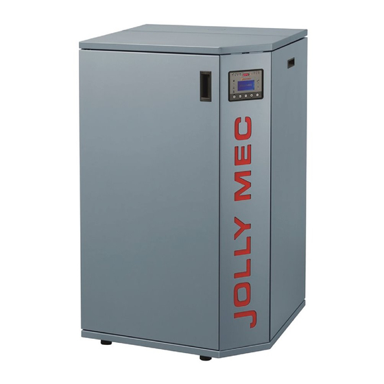
Summary of Contents for Jolly Mec MEC 21-18 kW
- Page 1 BOILER MEC 21-18 kW I N S T A L L A T I O N , U S E A N D MAINTENANCE MANUAL To be kept by the purchaser Pellet Boiler...
- Page 2 Dear Customer, thank you for having chosen to heat and save with a Jolly Mec product. Please carefully read and keep this sheet before using the equipment. This sheet provides necessary information and suggestions on how to correctly install, use, clean and maintain the product.
-
Page 3: Table Of Contents
TABLE OF CONTENTS CHAP.01 PREMISES........................... 4 01.1 WARNINGS ..............................4 01.2 SYMBOLOGY ............................... 5 01.3 APPLIED STANDARDS ..........................5 01.4 USE AND STORING OF THE INSTALLATION AND MAINTENANCE MANUAL ......... 7 01.5 WARRANTY AND MANUFACTURER’S LIABILITY..................7 CHAP.02 ACCIDENT PREVENTION / SAFETY REGULATIONS .............. 8 02.1 GENERAL CONSIDERATIONS ........................ -
Page 4: Chap.01 Premises
CHAP.01 PREMISES 01.1 WARNINGS • Familiarity and compliance with the instructions given in this manual will ensure quick installation and correct use of the appliance. • Read the manual attentively before commencing installation, and be certain to follow the directions it contains, otherwise the war- ranty could be invalidated and the performance and safety of the appliance jeopardized. • The installation manual is an integral part of the product and must be given to the user. • It must be kept in a safe place and consulted carefully, as all of the warnings provide important information on safety during instal- lation, use and maintenance. • Incorrect installation of the appliance could cause damage and injury to people or animals, for which the manufacture cannot not be held liable. • Installation shall be performed by qualified operators in accordance with the regulations in force in the Country of installation. • The manufacturer declines any contractual or non-contractual liability for damages caused by errors in installation or use of the appliance or failure to follow the instructions contained in this manual. • All rights on the reproduction of this technical manual are owned by Jolly Mec Caminetti S.p.A. The descriptions and illustrations provided in the following publication are not binding. • reserves the right to make any modifications that may be deemed appropriate. • Jolly Mec Caminetti S.p.A This manual cannot be given to third parties for perusal without the written permission of • Jolly Mec Caminetti S.p.A • The technical directions for installation contained in this manual should be considered as basic requirements. Regulations in some countries may be more restrictive; in this instance, comply fully with the regulations prevailing in the country of installation (all laws and local bylaws must be observed when installing and using the appliance, including those referring to national and European standards). -
Page 5: Symbology
01.2 SYMBOLOGY In this manual, points of considerable importance are marked with the following symbology: INSTRUCTION: Instructions regarding the correct use of the appliance. WARNING: This point is particularly important. An important point regarding behaviour for preventing injury and damage to DANGER: materials is expressed. - Page 6 In the UK, the product must be installed, operated and maintained complying with the following regulations and legislations: • BS 7671 Requirements for electrical installations • EN 806 Specifications for installations inside buildings conveying water for human consumption Part 1 General Part 2 Design...
-
Page 7: Use And Storing Of The Installation And Maintenance Manual
01.4 USE AND STORING OF THE INSTALLATION AND MAINTENANCE MANUAL • Recipients of the manual The use and installation manual is addressed to users responsible for the installation, operation and maintenance of the stove; particular attention must be given the parts of the manual concerning safety. If the product is subsequently resold, the user is requested to hand over this sheet and to inform the manufacturer of the name of the new owner, so that the latter may receive any updates issued. -
Page 8: Chap.02 Accident Prevention / Safety Regulations
CHAP.02 ACCIDENT PREVENTION / SAFETY REGULATIONS 02.1 GENERAL CONSIDERATIONS • The manual refers to essential aspects of the directives, regulations and dispositions on using the machine, summarising its most significant points. • General legal regulations and mandatory rules regarding injury prevention and environmental protection must be observed. -
Page 9: Safety Regulations For Extraordinary Maintenance And Installation
• In alarm status for failed start up, do not try to restart the stove until the firebox has been thoroughly cleaned. • The appliance must always be started up with the firebox empty, without pellets and without unburned fuel from previous use. -
Page 10: Equipment For Operators And Maintenance Personnel
• The power cord plug must be connected only AFTER the conclusion of the installation and assembly of the device, and must remain accessible after installation if the device does not have a suitable and accessible double-pole switch. • Personnel assigned to handling the machines and equipment must always wear industrial gloves and boots. •... -
Page 11: Chap.03 Handling And Transport
CHAP.03 HANDLING AND TRANSPORT 03.1 RECEIVING GOODS The machine is delivered on a pallet, packed in a card board box with a cellophane hood. when receiving merchandise, check that: • all packaging is intact. • all of the merchandise indicated on the delivery bill has actually been delivered. •... -
Page 12: Chap.04 Ecological Regulations
CHAP.04 ECOLOGICAL REGULATIONS 04.1 WASTE MATERIALS AND THEIR DISPOSAL Spare parts replaced during the machine’s product life are to be considered waste and must be taken to special collection centres or entrusted to authorised disposal centres. Ashes must be placed in a metal container with a sealed lid. The closed container must be placed on a non-combustible base and kept away from combustible materials until all the embers have been extinguished. -
Page 13: Chap.05 Description
Pellets are feed from the bottom, directly in the basket through a double worm screw driven by gear motors. The MEC 21-18 kW Pellet Boiler can heat an entire home in total autonomy over an area up to 130 m (or higher in the case of using a buffer). -
Page 14: Product Identification
05.2 PRODUCT IDENTIFICATION t is COMPULSORY to indicate the product MODEL, the LOT number and SERIAL NUMBER in all communications with the Manufacturer. Identification numbers are printed on the adhesive plate located on the back of the stove as illustrated. Stove performance values measured during inspection tests according to the indicated reference and EC markings are also included on the plate. -
Page 15: Chap.06 Technical Data
CHAP.06 TECHNICAL DATA 06.1 HOMOLOGATION Technical specifications resulting from laboratory tests conducted according to EN 303-5:2012 test methods at the CERTIFICATION institute. Cod. Descrizione Simbolo Valore Burnt heat output 20,64 Nominal heat power 18,58 Minimal Nominal heat Power Maximum Power consumption 4,23 Kg/h Minimum output consumption... -
Page 16: Recommended Fuels
06.2 RECOMMENDED FUELS WARNING PELLET QUALITY IS VERY IMPORTANT; PLEASE READ THIS SECTION CAREFULLY A pellet product’s performance is significantly linked and highly influenced by the type and quality of wooden pellets that is burned. It is important to choose pellets that have no debris or impurities. The Association of Pellet Manufacturers with the Italian Thermotechnical Committee have established standards for identifying pellets in terms of energy*. -
Page 17: Components
06.3 COMPONENTS The stove is delivered in a dust-proof cellophane hood secured in a wooden crate and with the following additional components: • Installation, use and maintenance manual • Use and maintenance accessories (see CHAP.08.6 -MANUTENZIONE ORDINARIA (A cura del cliente) •... -
Page 18: Optionals
06.4 OPTIONALS Automatic closing box for external air passageway: Insect- proof grate 230 x 230 mm: Installed on the external air passageway, it only allows for air Installed on the exterior of the comburent air intake, it prevents intake when actually necessary, closing the cold air passage insect entrance within the home. The mesh must be periodically when the generator is not running to thus avoid cooling the cleaned since dust, pollen or humidity can obstruct air passage installation room... -
Page 19: Dimensions
Auxiliary pellets tanks: For a greater autonomy it is possible to add a high capacity pellets container (400 or 700 kg) fitted with a screw conveyor loading. The figure below shows an example of positioning an auxiliary pellets container adjacent to the boiler. The slope of the pellets chute (PVC pipe) must never have angles of less than 45 °. -
Page 20: Chap.07 Positioning And Connections For The Installer
CHAP.07 POSITIONING AND CONNECTIONS FOR THE INSTALLER 07.1 HYDRAULIC CONNECTION AND EXTERNAL AIR INTAKE SETTINGS The device must only be installed indoors and on surfaces that can support the load. If the existing construction does not meet this requirement, it will be necessary to take appropriate measures (e.g. installing a load distribution plate). The appliance must be installed in an area where the appliance itself, gas exhaust pipes and flue can be easily accessed for maintenance. -
Page 21: Flue Or Fume Exhaust System
07.2 FLUE OR FUME EXHAUST SYSTEM The flue or fume exhaust system is a fundamental element for the proper functioning of the stove and must comply with the requirements of The Building Regulations Part J and with the following general standards: EN1856-1 Chimneys. - Page 22 Datum for horizontal measurments Datum for 150 mm vertical max. measurments Regulated building Adjacent building The datum for vertical measurments is the point of discharge of the flue, or 150 mm above the insulation, whichever is the lower Point Where flue passes through Clearances to flue outlet weather surface (Notes 1, 2) At or within 600 mm of the ridge At least 600 mm above the ridge...
-
Page 23: Installation Room Ventilation
Supporting the weight of the flue with the appliance union is strictly forbidden. Use specific stands or independent supports for this purpose. To install other combustion devices in the same room where the pellet appliance is installed, refer to UNI 10683 and UNI 7129 installation regulations. -
Page 24: Hydraulic Kit
07.4 HYDRAULIC KIT . 1 illustrates hydraulic kit components without DHW production, standard pre-installed on the MEC 21-18 kW boiler. Following is an itemised list of these components: 8 litre expansion tank Heat circulation pump High efficiency circulating pump Pressure transducer... -
Page 25: Back Panel
07.5 BACK PANEL External probe socket unit (F . 1): A Connection for any external contact to turn the water heater on and off B Terminal for remote room probe connection. In this case, the internal probe must be disconnected. C Terminal for water heater temperature probe connection D Terminal for high Puffer temperature probe connection E Terminal for low Puffer temperature probe connection... -
Page 26: System Configurations
07.6 SYSTEM CONFIGURATIONS Different hydraulic system configurations are possible with the MEC 21-18 kW boiler to allow for better operations based on the system solution adopted in the installation phase. This setting must be made by the installer or by the the specialised Technical Service Centre. - Page 27 CONFIGURATION 3 – Zone heating - Configuration identical to CONFIGURATION 1, with the addition of a zone module to manage a system with up to four zones per module, with zone valves or zone circulators. If the module is used, parameter Pr90 must be activated in the TECHNIC SETTINGS in the SETTINGS GENERAL page, setting the value to ON.
- Page 28 CONFIGURATION 6 – Boiler – The boiler is connected to the heating system and in parallel with an accumulation tank for DHW production. In this configuration, the heating part is identical to the functions described in CONFIGURATION 1 while the boiler takes precedence over the heating system request.
-
Page 29: Electric Connections
07.7 ELECTRIC CONNECTIONS Connect the 230Vac 50Hz line with the proper cable with plug, supplied with the appliance, which powers up the control unit and all the appliance’s electrical components. The stove is fitted with a current socket with fuse, a spare fuse in the drawer and a mains switch. In the event that the control unit does not switch on, even after turning the switch to “I”... -
Page 30: Control Unit Electrical Wiring Diagram
07.9 CONTROL UNIT ELECTRICAL WIRING DIAGRAM WARNING Electrical connections must be carried out by skilled personnel according to the regulations in force (2014/30/UE and 2014/35/UE). 23 24... - Page 31 NOTE The representation of the components is approximate, but they can change in terms of shape. 14 13 Pos. 8) Only for system diagram 6...
- Page 32 Following is a list of electrical components illustrated in the layout on the previous page ITEMIZED TABLE POSITION CODE DESCRIPTION DISPLAY/12 Remote control QUA/PELLET/2 Electronic card PRESA/1 Mains socket CAVO/14 Mains Cable RESISTENZA/6 Resistance of ignition MOTOR/4 Mechanical cleaner CIRCOLATORE/1 Water circulating Pump G/CONDENSATORE1 Condenser vent fumes...
-
Page 33: Chap.08 Use And Maintenance For The User
CHAP.08 USE AND MAINTENANCE FOR THE USER 08.1 BOILER FUNCTIONS The boiler electronically controls pellet combustion and water distribution to utilities. Pellets are taken from the storage tank by the gear motor driven auger and transported directly to the combustion basket by a second auger driven by another gear motor. - Page 34 The LED located above the button 1 has several meanings according to the related boiler states: The boiler is running GREEN Flashing GREEN The boiler is switching off, stays in alarm state or kept an alarm memory The boiler is shutdown The boiler has no power supply.
- Page 35 The flame symbol placed next to the related symbols indicates that: The boiler is working for the heating system The boiler is working for DHW production The boiler is working for the thermal buffer storage tank The display is divided into menus and sub-menus that can be scrolled using the control unit keys. In short, main menus and their functions are: MENU 00 - SET TEMPERATURE Menu for work temperature setting...
- Page 36 MENU STRUCTURE The main screen shows both values of room and water set temperatures as well as the working status of the boiler. From the main screen: - with the MANUAL Mode (settable in the MENU 00), the required power level (between 5 available) can be set by pushing key 3 or 4.
- Page 37 MENU 01 – CLOCKTIME SETTING Is used to set the current date and time, which is necessary for a correct operation of the timer thermostat (settable in MENU 02). Press 2 to access the pages of the relevant submenu. M01-001 DAY To select the current day of the week, use Keys 3 and 4 and press Key 5 to set the displayed value and move to the next page.
- Page 38 MENU 02 - TIMER THERMOSTAT SETTING Is used to enable or disable the operation of the timer thermostat and related programs; press key 2 to access the pages of the relevant sub-menu. M02-01 TIMER THERMOSTAT RELEASE Is used to enable or disable the operation of the timer thermostat.
- Page 39 M02-02-001 THERMOSTAT DAY TIMING Use keys 3 and 4 for choose whether enable or not the DAY TIMING Function; then press key 5 to confirm your choice and advance to the next page. M02-02-002 START 1 DAY Use Keys 3 and 4 to set the start time for the first operating time range permitted by the function and press Key 5 to confirm the selection and move to the next page.
- Page 40 M02-03-001 CHRONO WEEK Use Keys 3 and 4 to select to enable or disable the CHRONO WEEK function and press Key 5 to confirm the selection and move to the next page. M02-03-002 START PROG- 1 Use Keys 3 and 4 to set the start time for the first operating time range permitted by the function and press Key 5 to confirm the selection and move to the next page.
- Page 41 M02-04-001 CHRONO WEEK-END Use Keys 3 and 4 to select to enable or disable the CHRONO WEEK-END function and press Key 5 to confirm the selection and move to the next page. M02-04-002 START 1 WEEK-END Use Keys 3 and 4 to set the start time for the first operating time range permitted by the function and press Key 5 to confirm the selection and move to the next page.
- Page 42 If you use a commercial thermostat it is absolutely necessary to use the device with a dry contact closure to the boiler. The Jolly Mec module is also considered a thermostat, so when using the original Jolly-Mec device, set THERMOSTAT as the type of probe.
- Page 43 MENU 06 - DISPLAY SETTING Is used to change the display settings and the beep alarm signals of the boiler. Press key 2 to access the pages of the relevant sub- menus. M06-001 SET BUZZER Use Keys 3 and 4 to mute the buzzer when alarms occur and press Key 5 to confirm and move to the next page.
- Page 44 MENU 08 - BOILER STATUS The pages in the MENU 08 BOILER STATE consent to control the operating parameters of the boiler. Press key 2 to access the Menu Pages, use keys 3 or 4 to navigate through the various pages and key 1 to exit at the end. The page displays the fume temperature, the exhaust fan speed, the actual operating power, the auger loading duration and operating status.
- Page 45 MENU 09 - TECHNICAL SETTINGS Within this menu are contained pages for the parameterization of the boiler, into which only a specialised Technical Service Center can access by entering the appropriate access key. MENU 10 - SETTINGS REGULATION is used to modify several parameters of the boiler. To access the pages of the sub-menus press key 2. M10-001 REGULATE PELLET Use Keys 3 and 4 to adjust the quantity of pellets between -09 and -09 corresponding to ±3% each...
- Page 46 MENU 11 - MEMORY READING Allows you to read some data stored in the ECU memory. Press key 2 to access the pages of the relevant sub-menu. M11-01 TOTAL HOURS Total operating hours are displayed in this page. M11-02 PARTIAL HOURS Partial operating hours are displayed in this page.
- Page 47 M11-13-1 The first alarm saved in the memory is displayed in these two pages as illustrated in the example: AL00 Alarm code Alarm counter ALARM NAME Alarm name 12/05/13 Alarm date 10:50 Alarm time Similar to the previous pages, the other four alarms saved in the control unit memory are displayed in these pages.
-
Page 48: Boiler Start And Use
08.3 BOILER START AND USE After professionally installing the room ventilation system, the fume exhaust system, the hydraulic system and electrical system according to the relevant regulations, the specialised Technical Service Center can do the optional Commissioning Service. To use the boiler, fill the tank with pellets of the recommended quality, set the desired temperature and power (we recommend setting level 3) in MENU 00 and turn the boiler on with Button 1. -
Page 49: Safety Thermostat With Manual Reset
08.4 SAFETY THERMOSTAT WITH MANUAL RESET Two safety thermostats are installed on the boiler to read pellet burner and circulating water temperature and trigger to turn off the boiler when the relevant temperatures are faulty. The safety thermostats can shutdown the boiler when, for example, the burner overheats, triggering the pellet thermostat, or when there is no water circulation in the boiler, triggering the water temperature thermostat. -
Page 50: Tips For The User
08.5 TIPS FOR THE USER • If condensation appears inside the boiler, the causes could be: The heat pump is set too low (recommended minimum threshold 60°- 65°) Poor draught by the flue (clean the flue) Insufficient comburent air (check comburent air conduit) •... -
Page 51: Ordinary Maintenance (By The Costumer)
08.6 ORDINARY MAINTENANCE (by the costumer) WARNING Before starting any type of cleaning, switch off the main switch and make sure that the boiler is cold. Never restart the stove before completing these operations and correctly reassembling all components. Cleaning tools supplied Cleaning brush Flue cleaning brush Heat proof glove... - Page 52 Cleaning the glass Clean the glass every day with a damp sponge or paper towel . 6-7). If the glass becomes dirty with black smoke, the pellet basket is probably dirty or the combustion air must be increased. Be careful not to use overly aggressive product to avoid ruining the paint.
- Page 53 Boiler body cleaning . 20 Remove the basket and deflector (as described in points 4. Brazier removal for cleaning and 5. Fume deflector cleaning and removal). Use the supplied swap and brush to clean the exchanger, letting dust drop into the pan (F . 20). Remove the ash pan, empty it and accurately clean (as described in point 7. Ash pan removal and cleaning).
-
Page 54: Scheduled Preventive Maintenance (To Be Done By A Specialised Technical Service Center)
10. Opening and Cleaning the pellets tank: . 33 . 34 Leaving the outer front boiler door open, lift the lid of the pellet hopper and accompany it until it stops in vertical (Fig. 33-35). Each approximately 1000 kg of pellets burnt, empty the pellets inside the tank and verify that there is no excessive deposit of sawdust (Fig. -
Page 55: Chap.09 Fault Diagnosis And Troubleshooting
CHAP.09 FAULT DIAGNOSIS AND TROUBLESHOOTING 09.1 PROBLEMS WARNING In accordance with the laws in force on safety for electrical appliances, a specialised Technical Service Center or qualified personnel must obligatorily be contacted for all installation, maintenance or interventions that require access to electrical parts. -
Page 56: Alarm Messages
09.2 ALARM MESSAGES Following is an overview on appliance alarms linked to the probable causes and some potential solutions. If an alarm occurs with a certain frequency, contact a specialised Technical Service Center. Alarm code Alarm test Alarm cause Main solution • No power supply. • Make sure the electrical connection between the AL 1 POWER socket on the appliance back and power cord is... - Page 57 Alarm code Alarm test Alarm cause Main solution • Water temperature in the stove exceeded 85°C. • Make sure the pump outlet to the system heating AL 10 STOVEH2O circuit is open in the event of dissipation, that there OVERHEAT are not passageway obstructions due to zone solenoid valve triggered by external components.
- Page 58 Each safety alarm shuts down the stove. However, not all alarms indicate actual danger must are just warnings or alerts. For this reason, stove shutdown is not immediate but occurs after the auger empties. An additional combustion period (about 10’) follows the shutdown signal to start the normal shutdown procedure.
- Page 59 NOTE...
- Page 60 Via S.Giuseppe 2 - 24060 Telgate (Bg) Italy Tel. +39 035.83.59.211 Fax +39 035.83.59.203 www.jolly-mec.it - info@jolly-mec.it...
Need help?
Do you have a question about the MEC 21-18 kW and is the answer not in the manual?
Questions and answers