Advertisement
EN-KO Electronic Control Systems
AMF 4.0 AUTOMATIC MAINS FAILURE UNIT
AMF 4.0 genset control unit provides the functions, required in automatic mains failure
applications of gensets. It can be operated in automatic, test and manual modes. It contains
digital displays providing functions of all analog displays needed in generator panels. Device
digital displays show 3 phase mains and generator voltages, 3 phase generator currents, mains
and generator frequencies, battery voltage, oil pressure (bar), engine temperature and engine
hour. Generator is monitored constantly and when generator or mains values exceed the limits
adjusted in the parameter menu, necessary actions are taken and alarm is activated. Last ten
alarms are recorded in the device memory. All operating modes and timings can be adjusted
in the parameter menu. This flexibility is provided for different kinds of generator
applications.
FUNCTIONS
•
Manual engine starting and stopping
Mains monitoring, automatic start, stop and transfer switch functions
•
•
True RMS voltage and current measurements
•
Failures monitoring
•
Preheating
•
Manuel, automatic and test modes
Cost effective digital measurement displays
•
•
Recording of last 10 failure
•
Engine hour measurement and periodic service time warning
•
Manuel and automatic control of mains and generator contactors
•
Analog engine temperature and oil pressure measurement capability
Adjustable operating modes and timings via parameter menu
•
•
Analog bar graph, engine temperature and oil pressure displays
•
Adjustable measurement calibrations
Remote Start
•
USER MANUAL
(AMF 4.0 version 25)
AMF 4.0
I
R
Oil press
I
S
Esc
Esc
Esc
Esc
Temp
I
T
Battery
V
V
RS
R
V
V
S
S T
V
V
T R
T
MENU
Engine
hour
Freq
MAINS
GEN
DESCRIPTION
V1.36
Automatic Mains Failure
G
START
I / 0
I / 0
STOP
OFF
0
50
C
122
0
F
TEMPERATURE LEVEL
Critical
Level
OIL LEVEL
AMF 4.0/ENG/K.K./02
A
TEST
AUX.
V
0
100
C
0
212
F
Max.
Level
1
Advertisement
Table of Contents

Summary of Contents for EN-KO Electronics AMF 4.0
- Page 1 OIL LEVEL DESCRIPTION AMF 4.0 genset control unit provides the functions, required in automatic mains failure applications of gensets. It can be operated in automatic, test and manual modes. It contains digital displays providing functions of all analog displays needed in generator panels. Device...
- Page 2 • Mains contactor relay output • Auxiliary failure • Generator contactor relay output • Alarm relay output • 2 programmable auxiliary relay output • 2 programmable auxiliary input AMF 4.0 CONNECTION DIAGRAM LOAD MAINS GENERATOR Generator Current Generator Contactor Inputs...
-
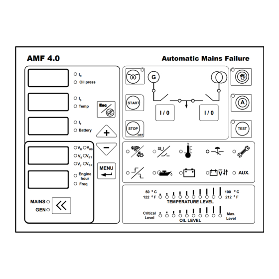
Page 3: Front Panel
EN-KO Electronic Control Systems AMF 4.0/ENG/K.K./02 FRONT PANEL AMF 4.0 Automatic Mains Failure Oil press START Temp I / 0 I / 0 STOP TEST Battery MENU AUX. Engine hour Freq MAINS TEMPERATURE LEVEL Critical Max. Level Level OIL LEVEL PreHeat Button (1): When genset doesn’t start in cold weathers, engine can be preheated... - Page 4 EN-KO Electronic Control Systems AMF 4.0/ENG/K.K./02 Mains Contactor (3): This button is used to control mains contactor. It cannot be closed if generator contactor is closed. Generator Status Led Lamp (4): • It is off, if engine isn’t running. • It is on, if engine is running •...
-
Page 5: Rear Connections
EN-KO Electronic Control Systems AMF 4.0/ENG/K.K./02 Up, Down Buttons (+, -): This button has two tasks. These are listed below. • It is used to select the values in the numerical displays. When you press first time led will be lit on the right of the display that is in selection mode. If you press second time you can change the value of display that is in selection mode. - Page 6 EN-KO Electronic Control Systems AMF 4.0/ENG/K.K./02 CONNECTIONS Terminal No Terminal Name Description Bat (+) Battery positive. Voltage must be between 9- 30 V Bat (-) Battery negative. Battery negative must be connected to earth. Com 1 Common terminal of preheat, fuel solenoid and cranking relays.
-
Page 7: Running Modes
EN-KO Electronic Control Systems AMF 4.0/ENG/K.K./02 Aux. Input 3 Multiple function auxiliary input. These inputs are activated if it is connected to battery negative. If this input is used for auxiliary input. Alarm will be shown as A3 in the display at the same time with auxiliary led indication. - Page 8 EN-KO Electronic Control Systems AMF 4.0/ENG/K.K./02 load. If operator wants to stop the engine in test mode panel must be returned to automatic or manual mode. In manual mode you can stop the engine by stop button. Manual Mode: If you press the manual button genset will be switched to manual mode. In manual mode all start stop and preheat operations, contactor control fulfilled by panel buttons.
- Page 9 EN-KO Electronic Control Systems AMF 4.0/ENG/K.K./02 ALARMS Alarms are divided to red and yellow alarms. Yellow alarms are for warning purposes and don’t stop the generator. Red alarms are serious and if occur generator contactor is opened and generator is stopped immediately.
-
Page 10: Parameter Menu
EN-KO Electronic Control Systems AMF 4.0/ENG/K.K./02 Mains failure: If mains voltage is lower than “mains under voltage failure” or is higher than “mains over voltage failure” mains failure occur and in automatic mode generator is started. If mains comes to normal condition (higher than “under voltage return”... -
Page 11: Operator Parameters
EN-KO Electronic Control Systems AMF 4.0/ENG/K.K./02 AMF 4.0 PARAMETERS Initial parameter settings are for genset model 10. These are as following table. For chosen genset model, parameter table can be loaded by means of parameter 69. Parameters that is changed according to genset models are specified in the next sections. -
Page 12: Technician Parameters
EN-KO Electronic Control Systems AMF 4.0/ENG/K.K./02 Mains failure delay 0-120 sec 3 sec Transfer delay 1-60 sec 1 sec Alternator contactor delay 0-90 sec 2 sec Mains return delay 2-900 sec 5 sec Preheat time 0-300 sec 0 sec Generator voltage failure delay... -
Page 13: Calibration Parameters
EN-KO Electronic Control Systems AMF 4.0/ENG/K.K./02 Cooling Time 0-600 sec 180 sec Fail to stop delay 4-120 sec 30 sec Engine stabilization time 2-60 sec 10 sec Engine protection delay after 1-60 sec 3 sec stopping Current transformer primary 5-900... - Page 14 EN-KO Electronic Control Systems AMF 4.0/ENG/K.K./02 P15 → 1 P45 → 3 P52 → 1 P53 → 0 P62 →100 P64 → 48 P67 → 9 P68 → 15 P62 →100 P64 → 43 P15 → 1 P45 → 3 P52 →...
-
Page 15: Parameter Descriptions
EN-KO Electronic Control Systems AMF 4.0/ENG/K.K./02 PARAMETER DESCRIPTIONS Parameters Description Operator Parameters Operator menu password Operator password can be changed by this parameter Temperature unit This parameter selects coolant temperature unit shown in the display. According selected unit “high coolant temperature level“... - Page 16 EN-KO Electronic Control Systems AMF 4.0/ENG/K.K./02 generators. Panel doesn’t control this input for 2 minute after engine start. After 2 minute if input is still active panel gives alarm, open generator contactor, cools engine then stop generator. If oil pressure sender that has both sender and switch is used, switch terminal must be connected to this input and this parameter is disabled.
- Page 17 EN-KO Electronic Control Systems AMF 4.0/ENG/K.K./02 method output relay de-energizes. At startup when you supply battery to panel this relay energizes and when output is activated relay energizes. If this parameter is selected as 1, when output activates, output relay energizes.
- Page 18 EN-KO Electronic Control Systems AMF 4.0/ENG/K.K./02 started in auto mode. Mains failure delay is waited before mains failure. P38 Generator under voltage failure If generator voltage fall below this limit under over voltage alarm occur. Failure occurred after generator voltage failure...
- Page 19 EN-KO Electronic Control Systems AMF 4.0/ENG/K.K./02 second. In engine stopping condition stop output is activated as 2 second cycling pulses. P53 Charging alternator If parameter is adjusted as “0”. Charge alternator failure doesn’t occur and crank doesn’t disconnected by charge alternator.
- Page 20 EN-KO Electronic Control Systems AMF 4.0/ENG/K.K./02 Enter model number to load parameter table of selected genset model. P70 Periodic service time This parameters selects After how many running hour periodic service alarm will be given P71 Engine hour adjustment Engine hour is adjusted by this parameter.
-
Page 21: Specifications
EN-KO Electronic Control Systems AMF 4.0/ENG/K.K./02 SPECIFICATIONS 9-35 VDC Power Supply 140 mA (all relays are de-energized) Ambient -10°C / +70°C Temperature Relative Humidity %10-%95 non-condensing For cranking, fuel solenoid, preheating and auxiliary outputs max. 12V/24VDC 6 A, For mains and generator contactor relays max. - Page 22 EN-KO Electronic Control Systems AMF 4.0/ENG/K.K./02 Dimensions in mm " Specifications are subject to change without notice."...
Need help?
Do you have a question about the AMF 4.0 and is the answer not in the manual?
Questions and answers