Table of Contents
Advertisement
Advertisement
Table of Contents

Related Manuals for Garz & Fricke CUPID 7.0" Open Frame

Summary of Contents for Garz & Fricke CUPID 7.0" Open Frame
- Page 1 CUPID 7.0" Open Frame Manual For PCB revision 0.7 or for HW 1.1 or later...
-
Page 2: Table Of Contents
CUPID 7.0" Open Frame Manual Content Introduction Safety Hints Product Introduction Product introduction Type plate and device information Related documents and online support Product Description Technical data PCB design Installation and start up Connection Scheme External interfaces and Schematics Applies for all interfaces Ethernet (X24) Power (X1) Digital I/O (X14) -
Page 3: Introduction
CUPID 7.0" Open Frame Manual 1 Introduction Thank you very much for purchasing a Garz & Fricke product. Our products are dedicated to professional use and therefore we suppose extended technical knowledge and practice in working with such products. The information in this manual is subject to technical changes, particularly as a result of continuous product upgrades. -
Page 4: Safety Hints
CUPID 7.0" Open Frame Manual 2 Safety Hints Please read this section carefully and observe the instructions for your own safety and correct use of the device. Observe the warnings and instructions on the device and in the manual. Garz & Fricke embedded systems have been built and tested by us and left the company in a perfectly safe condition. -
Page 5: Product Introduction
CUPID 7.0" Open Frame Manual 3 Product Introduction This document is applicable for hardware revisions 1.0 or later of the CUPID SERIES and thereon based customized variants. Please note that customized variants might possibly not support all features listed herein. Please find the hardware version grid in Annex B: Product introduction... -
Page 6: Related Documents And Online Support
CUPID 7.0" Open Frame Manual Related documents and online support This document contains product specific information. Additional documentation is available for the use of embedded operating systems and the related tool chain and the RedBoot BIOS. Title Link to Garz & Fricke Website Description Contains relevant information about RedBoot User Manual... -
Page 7: Product Description
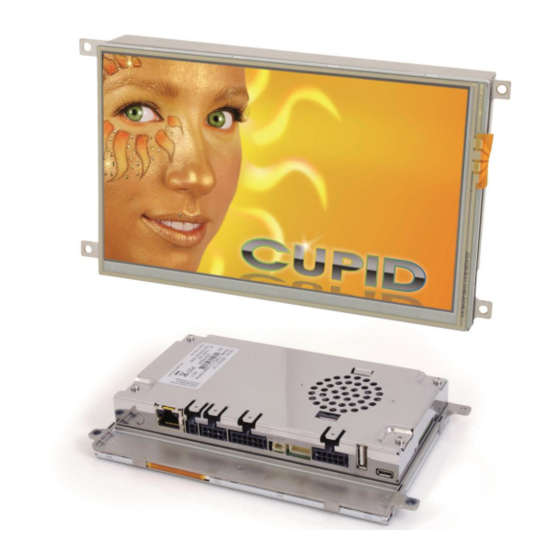
CUPID 7.0" Open Frame Manual 4 Product Description This drawing is meant for your orientation. For drawing please refer to Annex C: Mechanical specifications You will get 3 D Modell (CAD) Drawings after signed a NDA contract. Installation frame Display with resistive touch Reset switch SD-card slot Power LED... -
Page 8: Technical Data
CUPID 7.0" Open Frame Manual Technical data Class Freescale ARM11R ARM1136JF-S™ i.MX357 Type/Clock 532 MHz Integrated Vector Floating Point Unit; Features VPU and openVG 1.1 GPU Depending on ambient temperature Standard time´s deviation: +/- 30 ppm at 25°C Memory NAND Flash 512 MB SLC 256 MB DDR SDRAM SRAM... - Page 9 CUPID 7.0" Open Frame Manual Power Supply and Consumption Nom. 24 ± 15% Supply [V DC] Max. 9 ~ 30 Consumption [W] Typ. 4.5 Type 3 V Li-Ion Type CR2032 Internal Backup Battery (RTC) >10 years, depending on application Housing Back Cover 1.4016 high quality steel, polished, 0.8mm Approximate Dimensions...
-
Page 10: Pcb Design
CUPID 7.0" Open Frame Manual PCB design As this manual describes an open frame version, only the external interfaces will be mentioned in the following chapter. Pos. Description Pos. Description Ethernet (X24) USB - Host (X34) Power (X1) USB - OTG (X20) Digital I/O (X14) SD card reader (X31) CAN/RS-485 Interface (X39) -
Page 11: Installation And Start Up
CUPID 7.0" Open Frame Manual 5 Installation and start up The content of this document is limited to explain the device connectors and how to access CUPID via FTP over your local area network (LAN) within a few seconds. For advanced hardware specifications and software support, please refer to chapter Product Link to Garz &... -
Page 12: External Interfaces And Schematics
CUPID 7.0" Open Frame Manual 6 External interfaces and Schematics Applies for all interfaces GPIO Characteristics DC Electrical Symbol Test Condition Min. Typ. Max. Unit Characteristics Ioh = –1 mA NVCC – 0.15 High-level output voltage Ioh = specified 0.8 × NVCC drive Low-level output Iol = 1 mA... -
Page 13: Ethernet (X24)
CUPID 7.0" Open Frame Manual Ethernet (X24) Name Description Level SPARE1 Power Supply (PoE) SPARE1 Power Supply (PoE) SPARE2 Power Supply (PoE) SPARE2 Power Supply (PoE) -
Page 14: Power (X1)
CUPID 7.0" Open Frame Manual Power (X1) Name Description Level Ground Nom. 24 ± 15% Vcc_In Input voltage Max. 9 ̴ 30 Header: Molex 43045-0200 Micro-Fit 2p Plug: Molex 43025-0200 Micro-Fit 2p, crimp contact Molex 43030-0007... -
Page 15: Digital I/O (X14)
CUPID 7.0" Open Frame Manual Digital I/O (X14) Name Description Level DIG_IN1 Input 1 Low Typ. 8.3 DIG_IN2 Input 2 3-36V High mA / 24 V GND_DIO Ground for digital IO group Common ground, can be bridged with GND_DIO, when galvanic isolation is not required DIG_OUT1 Output 1... -
Page 16: Can/Rs-485 Interface (X39)
CUPID 7.0" Open Frame Manual CAN/RS-485 Interface (X39) Name Description Level GND_CAN_RS485 Ground for CAN and RS485 group To enable CAN1-Termination, bridge CAN1_TERM with CAN1_H -24…+24 V CAN1_H CAN bus 1 high -24…+24 V CAN1_L CAN bus 1 low To enable CAN1-Termination, bridge CAN1_TERM with CAN1_L To enable RS485-Termination: bridge... -
Page 17: Speaker (X9)
CUPID 7.0" Open Frame Manual Speaker (X9) Name Description Level Speaker + Max. 1.5 W @ 8 Ω or 3 W @ 4 Ω Parallel to internal speaker Speaker - Header: JST S2B-PH-SM3-TB, side entry, RM = 2.0, 2-pin Plug: JST PHR-2, crimp contact BPH-002T-P0.5S... -
Page 18: Keypad/Spi (X21)
CUPID 7.0" Open Frame Manual Keypad/SPI (X21) Description Name Level Default mode Mode 1 Ground Ground Ground Ground KP_ROW0 Keypad row 0 Keypad row 0 KP_COL0 Keypad column 0 Keypad column 0 KP_ROW1 Keypad row 1 Keypad row 1 KP_COL1 Keypad column 1 Keypad column 1 KP_ROW2... - Page 19 CUPID 7.0" Open Frame Manual Keypad/SPI/I²C, multiplexed 1* Description Name Level Mode 2 Mode 3 1-10 Identical to standard (pls. see 4.9.1.) KP_ROW4 Keypad row 4 Keypad row 4 KP_COL4 Keypad column 4 Keypad column 4 KP_ROW5_DMA Keypad row 5 SPI Interrupt Request KP_COL5_SS1 Keypad column 5...
-
Page 20: Rs-232/Mdb (X13)
CUPID 7.0" Open Frame Manual RS-232/MDB (X13) RS-232/RS-232 Name Description Level Ground RS232_TXD1 Port#1: Transmit data (Output) RS232_RXD1 Port#1: Receive data (Input) RS232_RTS1 Port#1: Request-to-send (Output) RS232_CTS1 Port#1: Clear-to-send (Input) Ground RS232_TXD2 Port#2: Transmit data (Output) RS232_RXD2 Port#2: Receive data (Input) RS232_RTS2 Port#2: Request-to-send (Output) RS232_CTS2... -
Page 21: Usb - Host (X34)
CUPID 7.0" Open Frame Manual USB - Host (X34) Name Description Level Power supply 5 V/ Max 500 mA Data minus Data plus Ground Header: USB Type A USB - OTG (X20) 6.10 Name Description Level Power supply 5 V/ Max 500 mA Data minus Data plus Device ID... -
Page 22: Battery
CUPID 7.0" Open Frame Manual Battery 6.11 Name Description Level Supply Battery: CR 2032... -
Page 23: Document Revision History
CUPID 7.0" Open Frame Manual 7 Document revision history The information in this document is subject to change without prior notice in order to improve reliability, design and function and does not represent a commitment on the part of the manufacturer. Author Description Revision... - Page 24 CUPID 7.0" Open Frame Manual Technical Appendix For PCB revision 0.7 or for HW 1.1 or later...
-
Page 25: Annex A: Assembly Options And Accessory
CUPID 7.0" Open Frame Manual Annex A: Assembly options and accessory A-1 WIFI (USB) Some appliances require a wireless network connectivity. To be more flexible in regard of upcoming WiFi Standard and approbations, we decided not to place the functionality on board. Therefore we recommend an external USB (WL250N). -
Page 26: Cupid Open Frame Version M
CUPID 7.0" Open Frame Manual A-2 Cupid Open Frame Version M Cupid is also available as minor assembly version. For the details of the external connectors please use the main part on the pages Pos. Description Ethernet (X24) Power (X1) RS-232/MDB (X13) USB - Host (X34) USB - OTG (X20) -
Page 27: Sideways Usb Instead Of Sd-Card Reader
CUPID 7.0" Open Frame Manual A-3 Sideways USB instead of SD-Card reader Pos. Description USB-Host (X101) USB-OTG (X22/32) X 101 Name Description Level Power supply 5 V/ Max 500 mA Data minus Data plus Ground Name Description Level Power supply 5 V/ Max 500 mA Data minus Data plus... -
Page 28: Annex B: Hardware Revision Information
CUPID 7.0" Open Frame Manual Annex B: Hardware revision information This document is applicable for all products listed below. Please note that customized variants might possibly not support all features listed herein. Additional features are documented in specific attachments. Platform Article Number Marking on PCB CUPID 7.0”... -
Page 29: Annex C: Mechanical Specifications
CUPID 7.0" Open Frame Manual Annex C: Mechanical specifications C-1 Mechanical Drawings... -
Page 30: Annex D: Quality And Incoming Inspections
CUPID 7.0" Open Frame Manual Annex D: Quality and Incoming Inspections D-1 Display... - Page 31 CUPID 7.0" Open Frame Manual...
- Page 32 CUPID 7.0" Open Frame Manual...
- Page 33 CUPID 7.0" Open Frame Manual...
-
Page 34: Evaluation Criteria Of Standard Display Module
CUPID 7.0" Open Frame Manual D-2 Evaluation Criteria of standard display module Evaluated Zone 1: Areas in the immediate viewing area: dirt and dust enclosures / stains / striae / scratches from max. 500 µm (diameter) or 0.02 mm2 (surface), 5 pcs. per dm permitted, but no clustering. -
Page 35: Annex E: Battery
CUPID 7.0" Open Frame Manual Annex E: Battery E-1 Battery Specifications The internal baseboard is equipped with a Lithium battery (CMOS battery, type CR2032), which has a typical lifetime longer than 10 years. Typically we assemble one of the following batteries: Manufacturer Model Varta... -
Page 36: Replacement Of The Internal Battery
CUPID 7.0" Open Frame Manual E-2 Replacement of the internal battery The internal battery is placed as per figure below. For replacement, the SD-card and the back cover have to be removed. The device shall be opened by authorized and skilled personnel only. Danger of electric hazard! First before opening, please make sure that the unit is completely disconnected from any power supply, direct or indirect. -
Page 37: Annex F: Guidelines And Standards
CUPID 7.0" Open Frame Manual Annex F: Guidelines and Standards F-1 EMC Pretests The Garz & Fricke open frame products are OEM-products, which are intended for the integration in customer housings. Therefore regulations and requirements are subjected to different markets. To help you with the EMC Certification we did pretests for radiated emissions with the open frame products. -
Page 38: Annex G: Common Documentation
CUPID 7.0" Open Frame Manual Annex G: Common documentation G-1 Warranty hints Garz & Fricke embedded systems are subject to manufacturer’s guarantee as long as the products are handled with adequate care and caution and in accordance to this manual. The period of guarantee starts from the date of shipment The products are warranted against defects in material, quality and functionality within the guaranteed period. -
Page 39: Application Notes
CUPID 7.0" Open Frame Manual G-2 Application notes The products covered by this document are designed and manufactured for the following applications (I). If you intend to use these products in applications as quoted in (II) or (III) we highly recommend a personal contact with our consultants and/or technical sales team.
Need help?
Do you have a question about the CUPID 7.0" Open Frame and is the answer not in the manual?
Questions and answers