Table of Contents
Advertisement
Advertisement
Table of Contents

Subscribe to Our Youtube Channel
Summary of Contents for Seismic Source DAQlink III
- Page 1 DAQlink III System 24 bit Acquisition System User’s Manual...
- Page 2 Seismic Source Co. Seismic Source reserves the right to make changes and improvements to its products without providing notice. Trademarks DAQlink III and VScope are trademarks of Seismic Source Co. Seismic Source Co. 2391 East Coleman Rd. Ponca City, OK 74604...
-
Page 3: Table Of Contents
2 CABLE CONNECTIONS..................... 9 2.1 DAQlink III Unit Operation........................9 2.2 Single DAQlink III Configuration .......................10 2.3 Multiple DAQlink III Unit Operation ....................11 2.3.1 Rugged 10/100 Network Switch –......................12 2.3.2 Rugged Network Cable – ........................12 2.3.3 DAQlink III Battery Box – ........................13 2.3.4 Wireless Network Option –........................14... - Page 4 3.0 DAQlink III Quick Start Guide ......................26 4.1 DAQlink Setup............................27 4.1.1 DAQlink Order ..........................28 4.1.2 Copy to All ............................28 4.1.3 IP settings ............................28 4.2 DAQlink Configuration Standard Menus...................29 4.2.1 Device Acquisition Menu – Standard Menu..................30 4.3 DAQlink Configuration Advance Mode....................33 4.3.1 Device Acquisition Menu –...
- Page 5 6.1 DAQlink Continuous Recording ......................94 6.1.1. Vscope Auto Start Function......................94 6.1.2 DAQlink Auto Start Feature......................95 6.1.3 GPS Trigger on PPS ........................96 6.1.4 DAQlink III Timing - GPS ......................97 6.1.5 Continuous Recording Examples ....................98 6.2 Continuous Monitoring of data......................100 6.3 DAQlink Flash Card Download ......................101 6.3.1 Downloading Single Records ......................102...
- Page 6 7.4 Firewall..............................122 7.5 TCP/IP Verification ..........................123 8 SPECIFICATIONS AND OPTIONS ................124 8.1 Options ..............................124 8.2 DAQlink III Specifications .........................125 9 SCHEMATICS......................126 9.1 DAQlink Connector wiring ........................126 9.2 DAQlink panel wiring – Version 1.....................127 9.3 DAQlink panel wiring – Version 2.....................128 9.4 Trigger Input Circuit:.........................129...
-
Page 7: Introduction
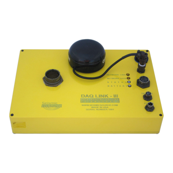
DAQlink Unit – Digital to Analog converter unit with Ethernet interface. DAQlink-III is a 24 bit • acquisition unit, with each box containing up to 24 channels. The DAQlink III is also capable of outputting an analog signal using a 16 bit D/A converter. -
Page 8: Daqlink Software Installation And Setup
DAQlink III manual • 1.3 Ethernet Setup The Ethernet must be setup before using the DAQlink III system Please refer to Ethernet setup section of the manual for detailed instructions on setting up the Ethernet settings on your computer. User’s Manual... -
Page 9: Cable Connections
Connect DAQlink III to computer with patch cable provided. • Connect 11-18 VDC supply to DAQlink III cable. • Note: The DAQlink III’s Battery LED’s will show the status of the battery voltage, • Green Flash – battery voltage is above 12 volts •... -
Page 10: Single Daqlink Iii Configuration
Connect DAQlink III to computer with patch cable provided. • Connect 11-18 VDC supply to DAQlink III cable. • Note: The DAQlink III’s Battery LED’s will show the status of the battery voltage, • Green Flash – battery voltage is above 12 volts •... -
Page 11: Multiple Daqlink Iii Unit Operation
The GPS time of the trigger event can be sent via the Ethernet connection to all of the DAQlink III units, if one DAQlink III unit triggers, then all of the DAQlink III units will be commanded to trigger at the same time. -
Page 12: Rugged 10/100 Network Switch
“Rugged Network cable” or direct from a battery. One Switch is required for every 100 meters of cable; Example a 48 channel system using two 24 channel DAQlink III units with 10 meter geophone spacing is setup. There is 240 meters between the two DAQlink III units. -
Page 13: Daqlink Iii Battery Box
2.3.3 DAQlink III battery box – Rugged water resistance battery box for use with the DAQlink III system. Normally sold with a 12 volt 20 amp hour battery. Provides connection for the DAQlink and Network telemetry (either wired or Wireless). Also provides mounting option for Wireless network. -
Page 14: Wireless Network Option
The Wireless Option includes one Wireless Access Point and one Wireless Station. Typically two DAQlink III units and a computer can be connected with only one Wireless Network Option. The wireless option works well in “line of sight” operation, distances up to 2 km can operate without any problems. -
Page 15: Ethernet Extender - Remote And Local Pair
2.3. Ethernet Extender – Remote and Local pair– This option is used to provide a wireless connection between multiple DAQlink III units. The Ethernet Extender pair includes one “Local” unit and one “Remote” unit. The Ethernet data is transmitted between boxes over a simple twisted pair cable. The distance between boxes can be up to one mile. -
Page 16: Networked Daqlink Iii Systems
2.4 Networked DAQlink III systems The DAQlink III unit can be configured as a 1 channel to 24 channel unit. Different networking options are available depending on requirement and terrain using a combination of Wired or Wireless Networking. User’s Manual... -
Page 17: Wired Network
2.4.1 Wired Network This pictures shows a single DAQlink III station setup in a wired telemetry mode. -
Page 18: Wired Network - 48 Channel Ethernet Extenders
2.4.2 Wired Network - 48 channel Ethernet Extenders Following picture is an example of a 48 channel DAQIII system using Ethernet Extenders. Up to 4 miles between extenders using twisted pair wire. User’s Manual... -
Page 19: Wired Network - 48 Channel System Using Rugged 10/100 Network Switches
2222 2.4.2 Wired Network - 48 channel System using Rugged 10/100 Network Switches Following picture is an example of a 48 channel DAQlink III system using 10/100 network switches. 100 meter maximum between network Switches. Power down cable. - Page 20 User’s Manual...
-
Page 21: Wireless Network
2.5 Wireless Network DAQlink III units can be connected using Wireless networks. This pictures shows a DAQlink III station and computer setup in a Wireless network configuration. -
Page 22: Wireless Repeater Station
2.5.1 Wireless Repeater Station This picture shows a DAQlink III units setup in Wireless network mode. This unit receives data with a Wireless. Station and Transmits to the next station with a Wireless Access. User’s Manual... -
Page 23: Wireless Network - 48 Channel System Using Wireless Network
2.5.2 Wireless Network - 48 channel System using Wireless Network Following picture is an example of a 48 channel DAQlink III system using Wireless network option. -
Page 24: Wireless Network - 72 Channel System Using Wireless Network
2.5.3 Wireless Network - 72 channel System using Wireless Network Following picture is an example of a 72 channel DAQlink III system using Wireless network option. User’s Manual... -
Page 25: Wireless Network - 96 Channel System Using Wireless/Wired Network
2.5.4 Wireless Network - 96 channel System using Wireless/Wired Network Following picture is an example of a 96 channel DAQIII system using Wireless and wired network options. -
Page 26: Configuring The Program
Setup Hardware 1. Connect Ethernet patch cable from DAQlink III unit to the Computer. 2. Connect DC power to 2 pin connector on DAQlink III unit ( 11 – 18 VDC). 3. Connect Analog Geophone Cable to 55 pin connector. -
Page 27: Daqlink Setup
Make sure the unit is enabled. A check mark by the serial number shows that the unit is enabled. Just left click the small box next to the serial number to enable it. Multiple DAQlink III units can be connected to one computer using standard network equipment (hubs, switches, wireless access points, etc). -
Page 28: Daqlink Order
The last octet is a number between 0-255. The number 0 and the number 255 are reserved and should not be used for a DAQlink III IP address. Only the numbers 1-254 should be used. The computer’s IP address should also be unique; it cannot have the same IP address as a DAQlink III unit. -
Page 29: Daqlink Configuration Standard Menus
DAQlink III unit is working properly. If the configuration window does not appear, it means that the DAQlink III unit selected is not responding. This is usually caused by improper TCP/IP settings, or Ethernet cable not plugged in properly. The computer or DAQlink III unit may need to be reset if the TCP/IP configuration has changed. -
Page 30: Device Acquisition Menu - Standard Menu
4.2.1 Device Acquisition Menu – Standard Menu The Acquisition Menu allows the following selections 1. Gain – This entry sets the pre-amp gain on the DAQlink III. Standard setting for Seismic acquisition is 16 a. Gain =1 maximum input is 3.58 volts peak to peak. - Page 31 Trigger Settings allows for two different trigger inputs 1. Auto Trigger (ReMi) - When this selection is enabled, the DAQlink unit will trigger immediately and will record and transmit data to the Vscope program without an external trigger 2. Trigger on Time Break (Hammer Switch) – When this selection is enabled, the DAQlink unit waits for a switch closure on the trigger input connector.
- Page 32 GPS Menu The GPS menu is used to setup the DAQlink III for GPS position and timing. Normally an external GPS unit is used. The baud rate selection is made with the Baud rate software switch. To use the standard Garmin GPS unit sold from Seismic Source, select External and 19.2K baud rate.
-
Page 33: Daqlink Configuration Advance Mode
4.3 DAQlink III Configuration Advance Mode When first installed, the Vscope program uses Standard menus. These menus provide all of the necessary options for normal seismic operation. The Advance menus can be selected in the Option – Preferences –Menu. Selecting Advanced Mode selects the advance menus. -
Page 34: Device Acquisition Menu - Advance Mode
This menu allows the user to setup the acquisition parameters for the selected DAQlink III unit. Up to 24 channels per DAQlink III unit are shown. The DAQlink III unit automatically checks the number of operating channels when the unit is reset. -
Page 35: Trigger Menu - Advance Mode
Threshold = 0.01 volts. The auxiliary Geophone input is wired to the 19 pin connector – pin M + and pin N - Trigger on PPS Pulse- In this mode; the DAQlink III uses the GPS time to trigger •... - Page 36 Figure 4.2.2 Device Trigger User’s Manual...
-
Page 37: Order Menu - Advance Mode
The order menu appears when a 24 channel DAQlink III is connected, ( NOTE: This menu is not active with 6, 12, or 18 Channel DAQlink III units). The order menu is used to arrange the channel numbers in each DAQlink III unit. This selection allows compensating for... -
Page 38: Device Analog Output - Advance Mode
4.3.4 Device Analog Output – Advance Mode The DAQlink III uses the Analog Outputs to generate test signals. For normal operation the output must be set to NONE. Figure 4.3.4 Device Analog Output User’s Manual... -
Page 39: Gps
The GPS receiver can be connected internally to the unit or can be connected to the external connection. Select the correct GPS configuration. The DAQlink III is designed to have an external GPS receiver connected to the 4 pin connector on the DAQlink III unit. - Page 40 When a valid GPGGA message is received (Must have valid position), then the data will update when the “Get Position Button” is pressed. A valid PPS pulse is required for the DAQlink III to trigger on “PPS” or “Trigger on GPS time” to operate.
-
Page 41: Daqlink Calibration
4.3.6 DAQlink III Calibration The DAQlink III preamplifiers can be set for different fixed gain settings. In addition to this fixed gain setting, there is a software gain setting that is set by the user in the acquisition menu. To compensate for the different gains on the amplifier boards, a software calibration number is entered at the factory. - Page 42 Optional Gains are available. Calibration Table below shows: Low Gain at 1.79 volts peak to peak ( 2 x less than standard) • High Gain is 0.22 volts peak to peak (about 2 x more than standard) • Figure 4.3.6a Device Calibration Calibration Table below shows: Low Gain at 7.16 volts peak to peak ( 2 x more than standard) •...
-
Page 43: Device Advanced Menu
Oscillator to “Automatic Correction”. This allows the precise PPS timing of the GPS unit to be used to adjust the internal clock on the DAQlink III unit. The Manual Value entry will show the current value being used by the DAQlink III unit. -
Page 44: Program Operation
Processing – will be displayed at the end of acquisition. • Also the Status Tab at the bottom of the display can be used to monitor status of the • DAQlink III units. To stop acquisition in progress select menu Acquisition->Stop or click Stop button or Press Ctrl T. -
Page 45: Projects
5.2 Projects The VScope uses projects to save program settings and to store acquired data. The projects are like folders used to sort and store different data. Each project saves its own configuration for acquisition parameters, plot selection, scaling options, and other VScope selections. -
Page 46: Database
5.3 Database 5.3.1 Loading Data from Database The VScope program has a built in database support. For this reason all of the data that acquired by the program is stored as records in a database rather than in separate files. This allows for greater flexibility with data manipulation, record searching and analysis. - Page 47 Toolbar buttons at the top of Database window help to find particular record. Import Records allows data to be imported into Database. Export Records allows selected records to Exported from the Database. Edit Comment (Ctrl E) – Use this button to view or edit the comment. Assign Source and Receiver Coordinates.
-
Page 48: Daqlink And Channel Configuration
5.3.2 DAQlink III and Channel Configuration Clicking the “DAQ Configuration” and the “Channel Configuration” buttons can show the DAQlink III Configuration and the Channel Configuration for the saved data. The DAQlink Configuration shows the acquisition parameters for each DAQlink III used in the selected record, also the GPS data will be shown if available. -
Page 49: Import And Export Data
5.3.3 Import and Export Data The import and export functions located in File menu allow for data to be exported or imported to different projects or to different applications. The VScope currently offers the option for the following import and export files. VScope data files (*.vs2) –... - Page 50 records can be selected by pressing ctrl A (or go to Edit- While in the database explorer, all Select All Menu). After selecting all of the records, you can eliminate records that you do not want to export. Move the mouse to the record that you would like to omit from the list. Hold the ctrl button and press the left mouse button once.
-
Page 51: Storing Data To Database
5.3.4 Storing Data to Database After acquisition is finished you can save new data to database. Select menu File->Save (Ctrl S). A window will appear where you can enter a comment for current record. By default this window displays a comment from the last record in the database. 5.3.5 Stacking Data in Database While in the Database menu, multiple records can be stacked together. -
Page 52: Inverting Data Before Stack - Shear Wave
5.3.6 Inverting Data before Stack – Shear Wave One method of Shear Wave acquisition is done by hitting one side of a plate and storing the data, then hitting the opposite side of the plate and storing the data. The second record is inverted and then the two records are summed to show only the Shear wave energy. - Page 53 After the one record has been inverted, then select the two records to stack, then press “Load Stack” button to view the two stacked traces. The stacked data can then be stored to the database.
-
Page 54: Real Time Inversion Of Data
5.3.6.1 Real Time Inversion of Data The data can also be inverted during acquisition with Positive/Negative button in the Toolbar. The polarity of all of the data is inverted when is shown. This extra Toolbar button is enabled in the Options – Preference - Stack Menu. The Stack Menu’s Enable Polarity Selection for Stacking will enable and extra button in the Vscope Toolbar which will invert all of the data. -
Page 55: Near Trace Gather
5.3.7 Near Trace Gather While in the Database menu, select the records to use for the Near Trace Gather by highlighting each record. After highlighting the desired records, select the “Near Trace Gather” option in the File menu. Enter the channel # for the near trace gather. This one channel from each record will be plotted. - Page 56 User’s Manual...
-
Page 57: Data View And Analysis
5.4 Data View and Analysis 5.4.1 Graph plot types Buttons on the toolbar and the View menu allow you to select different ways of signal representation on the graph plot. Shows time domain plot of acquired signal. - Page 58 Shows signal spectrum in frequency domain. The time window allows performing a spectrum analysis on a time window. An entry of 1 to 2 performs the spectrum on the data between 1 and 2 seconds. An entry of –1 to –1 performs analysis on the whole trace.
- Page 59 Select correlation to display correlation, phase of correlation, envelope of correlation, or spectrum of correlation. Also, correlated Seismic Plots can be displayed. The correlation will be performed using the channel defined in the DAQ units type field = Reference. Other channels can be selected with the assigned reference pull down menu. Seismic Plot can be shown in Vertical or Horizontal display.
-
Page 60: Plot Popup Menu
5.4.2 Plot Popup Menu The same selections are available in the plot popup menu. On any plot press the right mouse button to bring up the plot menu. Figure 5.4.2 Plot Popup Menu Axis allows changing of the x and y axis of the plot. Full view or ctrl +F zoom out completely to show all of plot. -
Page 61: Store Plot Menu
5.4.3 Store Plot Menu Store Plot – allows the current plot to be saved to memory and viewed later as an overlay to another signal. The first trace in a plot will be stored. The color and name of each stored plot can be changed in the Store Plot Menu. -
Page 62: Store All Plot Menu
5.4.3.1 Store All Plot Menu Store All Plots – allows the current plot to be saved to memory and viewed later as an overlay to another signal. All channels can be stored using the “Store All Plots” Function. Right click the Plot to bring up the “Store All Plot” Option. After storing all plots, a second group of plots will be displayed. -
Page 63: Seismic Plots
5.4.4 Seismic Plots There is an additional option for a Seismic Plot. When the signal traces plot is selected, the Seismic Plot option can be selected. The plot can be either Horizontal or Vertical. Also, the peak of the signals can be clipped to allow better viewing of multiple channels with large gains. Figure 5.4.4 Vertical Seismic Plot –... - Page 64 Pressing the right mouse button when it is on the graph, will pull up the plot popup menu. Select the Scale feature. The scale window allows the user to select different scaling options for the Seismic Plot. Absolute Max – Applies the same gain to every trace Equalize –...
-
Page 65: Setting Zoom Level
5.4.5 Setting Zoom Level Zoom buttons on the toolbar and the View menu help to adjust a view of a selected plot. Axis allows changing of the x and y axis of the plot. Full view or ctrl +F zooms out completely to show all of plot. To adjust zoom with the mouse press the left mouse button and make a box to zoom in on an area of the plot. -
Page 66: Additional Plot Functions
5.4.6 Additional Plot Functions Opens a new plot window Toggles selection of the remove DC feature. When enabled this feature removes the DC component from the input signal before plotting or analyzing data. Status of selection is shown in the Plot info window at the bottom of the screen. User’s Manual... -
Page 67: Filters
5.4.7 Filters High Cut, Low Cut and Notch filters can be setup and selected. The Tool bar can be used to select or unselect each filter. If the Toolbar button appears pressed in then the filter is selected. The setup for each filter can be found under the pull down menu Option – Preference. The pass band, and stop band frequencies for the Highpass and Lowpass filters can be set. -
Page 68: General Settings
5.4.8 General Settings The General Settings menu allows the user to select either the A/D units (Volts), or some other display unit which was setup in the DAQlink III configuration. For normal Seismic operation A/D units should be used. Show Caption Buttons – allows the Toolbar Menu to be easier to use. -
Page 69: Auto Save And Auto Start
Auto Start Acquisition can be enabled from the main menu with the Repeat Button. After the data is acquired from all of the selected DAQlink III units, the Vscope program automatically sends a new start command out to the selected units. -
Page 70: File Export Options
5.4.10 File Export Options File Export Menu allows the user to setup the following file export selections Short File Names - When selected the program uses the File Number and the • extension. Detailed File names – When selected the program uses the File number plus the •... -
Page 71: Stack Menu
5.4.11 Stack Menu Stack menu allows the user to setup the following automatic save operations. Auto Stack Records- When selected the program will automatically stack the • records. See Memory Function. Save Stack to Database – When selected the stacked data will be saved to •... -
Page 72: Lock And Unlock Menu Option
5.4.12 Lock and Unlock Menu Option The Lock menu option is normally not used. It is designed to lock the menu when operating in an automatic acquisition mode and accidental keyboard entries should be ignored. To unlock the keyboard, type “ssc” as the password. User’s Manual... -
Page 73: Noise Statistic Window
5.4.13 Noise Statistic Window The real time Noise Monitor Window can be selected by the “Open Noise Statistic” button on the tool bar, or by pressing ctrl F7. The Noise Statistic Window shows analysis of the current acquired data. The RMS, maximum, minimum, and DC levels of each trace are shown for the current record. -
Page 74: Real Time Noise Monitor
5.4.14 Real Time Noise Monitor “N” key is used to enable and disable the Real Time Noise Monitor. The Real Time Noise monitor provides a continuous monitor of the line noise. This graph is very useful in determine line noise between shots. The Y-axis needs to be selected to a fixed scale. -
Page 75: Status Information Tabs
5.5 Status information Tabs The Status information tabs at the bottom of the main window provide useful information about the current operation of the system. 5.5.1 Comment The Comment tab shows the current comment for the record. Figure 6.5.1 Comment 5.5.2 Record Information The Sweep information tab shows important information about the record. -
Page 76: Plot Information
The Status tab shows the status of the DAQlink IIIs connected to the system. This is very useful in troubleshooting wireless Ethernet connections. Figure 5.5.413 Status 5.5.5 Errors The Error tab shows any communications error or error detected by the DAQlink III unit. If an error occurs this tab is automatically displayed. User’s Manual... -
Page 77: Communication Tab
5.5.6 Communication Tab The communication tab shows the current status of the DAQlink III units that have been selected in the DAQlink setup menu. This is useful when using the wireless Ethernet option. Figure 5.14 Communication 5.5.7 Network Tab The Network Tab is used to show the current IP address that was detected when VSCope started. -
Page 78: Memory Window - Stacking Operation
5.6 Memory Window – Stacking Operation The memory window is used to stack multiple records in real time. Go to the Option – Memory selection to open the memory window. The Option – Preferences – Auto operation settings are also used to set up automatic stacking and storing of multiple records. Each record is stored in memory and can be saved to the database. -
Page 79: Memory Window
5.6.2 Memory Window Opening the Memory Window shows details of the stacking process. Figure 5.6.1 Memory Window The memory window tool bar is used to control the operations of the memory window. The memory clear button is used to clear all records from memory. Press this button before starting a new stack. -
Page 80: First Break Pick Feature
5.7 First Break Pick Feature The Edit -Picker menu or the button on the tool bar is used to enable the first break pick feature. With this feature enabled go to the point on the screen and left click the mouse. Figure 5.7.1 Picks on Seismic Plots User’s Manual... - Page 81 Right click on the screen and select pick table. The pick table will appear on the left side of the seismic plot. The time of each pick is shown in the table. The geophone spacing is entered at the bottom of the screen. The velocity will be computed using the picks and the geophone spacing.
- Page 82 The Edit – Geometry selection or the on the toolbar is used to select the geometry window. The X (distance) and Z (elevation) of each geophone is entered in the table. Figure 5.7.2 Edit Geometry Screen The File –Save pick selection is used to save the picks to a File. This pick file is in a standard format to be used by other processing software.
-
Page 83: Refraction Example Setup
5.8 Refraction Example Setup The Vscope software with the DAQlink III unit has been designed to be a very flexible system which has many options for setup. Once System is setup, all settings are stored in the “Project Settings”. When a new project is created, the current project settings can be copied to the new project. - Page 84 Auto Save Menu Options- Preference- Auto Save Menu Allows data to be automatically saved to database or exported to SEG-Y or SEG-2 data. Example shows saving all data to database and SEG-Y files. Large number of records in database can slow system. The database storing can be unselected to speed up system with large number of records.
- Page 85 File Export Menu Options – Preference – File Export Menu This menu selects the naming option for the SEG-Y file names.
- Page 86 Stack Menu Options – Preference- Stack menu This menu selects the options for the automatic stack function. Data stored in database can also be stacked at a later time to eliminate bad records. To speed up field acquisition, it is sometimes desirable to save all records and stack and review data in the office.
- Page 87 Real Time Noise Window The Real Time Noise Window can be used to determine the best time to do a refraction hit. Sometimes the Refraction study is done in an urban area with large ambient noise from airplanes, large trucks, etc. This ambient noise should be at a minimum when Hammer Hits are taken.
- Page 88 Typical Refraction Shot Screen Setup with Noise Monitor User’s Manual...
- Page 89 Acquiring Refraction data with Hammer Hits Press “Ctrl R” to enable the “Repeat Start” or “Auto Start” function of the system Press “A” – Starts Auto Sequence Wait for Real Time Noise Monitor to show Low Noise – (Press “N” to enable the real time Noise Feature) Hit Strike Plate with Hammer System will display first “Hit”...
-
Page 90: Vscope "Hotkeys
5.9 Vscope “HotKeys” The following “Hotkeys” can be used with the Vscope Program. These “HotKeys” allow quick access to functions without having to use the mouse and the mouse buttons. “A” – Start Acquisition “ESC” – Stops Acquisition – also exits some menus “Ctrl S”... - Page 91 Seismic Plot “+” – Increase amplitude “-“– Decrease amplitude “*” – Stretch in time “/” – Compress in time “Home” – To the first trace “End” – To the last trace “PgUp”/”PgDn” – Move up and down Arrows – Move cursor Ctrl + Arrows –...
-
Page 92: Geophone And Line Test
5.10 Geophone and Line Test The DAQlink III has a built in Geophone Test and Line test feature. This test performs a “Pulse Test” on all of the geophones. The results of the test are shown on a bar graph at the bottom of the Screen. -
Page 93: Multiple Daqlink Triggering -- Trigger On Time Feature
For Multiple DAQlink III triggering a special “Trigger on Time” feature is built in on all modes. When one DAQlink III unit triggers a special “Trigger on Time” message is sent to all other DAQlink III units through the Ethernet Network. This message is received by all of the other DAQlink III units and they will trigger and send data back to the main computer. -
Page 94: Advanced Features
Vscope and DAQlinkIII system. The Vscope auto start allows the software program to restart the DAQlink III unit. The DAQlink III auto start allows the DAQlink III to auto start itself without being commanded from the Vscope program. -
Page 95: Daqlink Auto Start Feature
6.1.2 DAQlink III Auto Start Feature The DAQlink III also has an auto start feature. This feature is enabled in the Options- Device-DAQ setting menu. Advance Mode must be selected in the Option-Preference menu to enable this screen. There are three selections in this menu 1. -
Page 96: Gps Trigger On Pps
6.1.3 GPS Trigger on PPS The DAQlink III unit can be set to trigger on the GPS PPS clock. First the trigger on PPS pulse must be selected in the trigger selection, and then the Timer values must also be selected. -
Page 97: Daqlink Iii Timing - Gps
PPS pulse from the GPS unit to start using the trigger on PPS mode. After this first valid PPS, the internal clock of the DAQlink III units are used to trigger the later records. -
Page 98: Continuous Recording Examples
Example 1: Setup DAQlink III for Autonomous continuous recording using GPS time. With the following setup the DAQlink III will record the data to the internal Flash memory. The data must be downloaded to the Vscope computer after recording is completed. - Page 99 The internal GPS oscillator should also be adjusted to GPS time. This allows for the long records to have correct timing. This selection is found in the Device- Options-Advanced settings tab.
-
Page 100: Continuous Monitoring Of Data
Example 1 msec sample rate 1 second record Set up the DAQlink III to record. Setup system for appropriate trigger method. Either setup for auto trigger for continuous monitoring, or use actual trigger to monitor actual event. Select signal graph and go to axis setup. -
Page 101: Daqlink Flash Card Download
6.3 DAQlink Flash Card Download The DAQlink III unit stores all data to an internal compact Flash card. The records can be downloaded to the Vscope program after data has been acquired. Before using the Flash Card option, it is best to reset memory in the Flash Card. -
Page 102: Downloading Single Records
6.3.1 Downloading single records To download a single record from the DAQlink III Flash card memory, go to Options- Download Menu. After pressing the “Get List of Records” button, a list of all of the stored data will appear. Select record to be downloaded from the list by highlighting the record. Press Download selected. -
Page 103: Downloading Multiple Records
The selected records will be stored to the database. If the Time of the record matches another Time already in the database then the new record will be added to the existing record. This allows data from multiple DAQlink III units to be combined together in the database. -
Page 104: Compact Flash Card Operation
6.3.3 Compact Flash Card Operation The DAQlink III larger Compact Flash (CF) cards have 1 to 3 % bad sectors. These bad sectors are identified when the card is formatted, and these sectors are mark. It is important that the CF Card be formatted when installing new CF cards or moving a CF card from one DAQlink III to another unit. -
Page 105: Compact Flash Storage
The number of records that can be stored depends on the sample rate, number of channels, and record length. When the memory is full, the DAQlink III starts over at the beginning and overwrites the stored data at the beginning of the Flash Card memory. - Page 106 Example 2: Sample Rate = 1/16 msec Record Length = 1 second # of channels = 24 Number of bytes/ record = (16,000 SAMPLES/SEC) * (3 BYTES/SAMPLE) * 24 CHANNELS = 1,152,000 BYTES/SEC Theoretical Maximum Storage: 2GB should hold 1736 one-second records 8GB should hold 6944 one-second records Actual Storage results 2 GB recorded 1538 records in list (0.886 of the 1736)
-
Page 107: Speed Of Downloading
6.3.5 Speed of Downloading A large CF card will take a long time to download data to the database. Example: 24 channels at 1/16 msec sample rate with 1 second record. 100 records 82 seconds 1.30 hours for 8GB Downloading Data from CF card 1) First go to the Database Explorer ( File –... -
Page 108: Changing Data In Database - Trace Order - Polarity
6.4 Changing data in Database – Trace order - Polarity The data in the database can be change by editing the values in the DAQlink III settings. 6.4.1 Changing Trace Order First open the file with the database explorer. Click on DAQ Config and Channel Config buttons to make the list of channels visible. -
Page 109: Changing Polarity Of A Trace
6.4.2 Changing Polarity of a trace First open the file with the database explorer. Click on DAQ Config and Channel Config buttons to make the list of channels visible. Click on the Calibration value of the trace to be inverted. Click on the Minus sign to invert the polarity. -
Page 110: Daqlink Iii Analog Output
6.5 DAQlink III Analog Output The DAQlink III unit has a built in Digital to Analog convertor. This D to A unit allows the DAQlink III to output “Test Waveforms” for testing of the DAQlink III unit. WARNING: The Analog Output is designed for Advanced Users Only. From Normal operation always set Analog Output to “NONE”... - Page 111 The Analog output signal can be connected to the analog section of the DAQlink III unit by selecting “Loopback” in the DAQlink configuration - Input selection. When “Loopback” is selected, the “Geophone Input” is not connected to the circuit., the analog input is connected only to the analog circuit of the DAQlink III.
-
Page 112: Viewing Detail Of Record
6.6 Viewing detail of record The details of the seismic record can be viewed by pressing “ctrl –alt –D” This screen is used for development of the program and should not be used by novice operators of the system. However, this screen may be useful in troubleshooting problems. User’s Manual... -
Page 113: Ethernet Setup
7 Ethernet Setup Normally, it is necessary to set up a fixed TCP/IP address for the computer to communicate with the DAQlink III unit. IP Address SET to FIXED IP ADDRESS – 192.168.0.101 All Firewalls Disabled 7.1 Windows VISTA Operation When using Windows Vista Operating System the VSCOPE program cannot be installed in the Program Files subdirectory. - Page 114 Select “Manage network connections” User’s Manual...
- Page 116 Right Click on the “Local Area Connections” and select “Properties” It is also recommended to disable all other Network connections. Highlight the other Network Connections (like Wireless) select “Connectivity” and Disable. User’s Manual...
- Page 117 Highlight the “Internet Protocol Version 4 (TCP/IP)” and Click on Properties button. Use following IP address: IP address 192.168.0.101 Subnet Mask 255.255.255.0 Press OK to accept entries.
-
Page 118: Windows Xp Ethernet Setup
7.2 Windows XP Ethernet setup With Windows XP computer setup in classic mode, the Ethernet setup is done by the following procedure: Go to the Control Panel and open the Network Connections. User’s Manual... - Page 119 Right Click on the Local Area Connection Icon and select properties. Scroll Down to the Internet Protocol TCP/IP selection and click on this icon. Click on Properties button. Use following IP address: IP address 192.168.0.101 Subnet Mask 255.255.255.0 Press OK to accept entries.
-
Page 120: Windows 2000 Ethernet Setup
It is sometimes necessary to reboot the computer to have the new address take effect. If the DAQlink III unit was previously communicating with a computer with a different address, then the DAQlink III unit must be reset (power off then on) for the unit to communicate to the new address. - Page 121 It is sometimes necessary to reboot the computer to have the new address take effect. If the DAQlink III unit was previously communicating with a computer with a different address, then the DAQlink III unit must be reset (power off then on) for the unit to communicate to the new address.
-
Page 122: Firewall
It is important to disable all Firewalls on the computer. Third party firewall from Norton, McAfee or other companies can completely disable the operation of the DAQlink III unit. Typically the Firewall will allow the “ping” command to operate, but will block all other commands and messages. -
Page 123: Tcp/Ip Verification
7.5 TCP/IP Verification To verify that the IP address is correct, select “Start”, then “Run”, then type in “CMD”. This starts the command prompt in Windows (This is similar to the old DOS command prompt). Type the command “ipconfig”. The current ip address 192.168.0.101 should be shown. Viewing the Network Tab at the bottom of the Vscope program can also check the IP address. -
Page 124: Specifications And Options
GPS clock. Analog Cables • o The DAQlink III unit has a 55 pin connector for the analog inputs. Various analog cable options are available for the end user. Power and Ethernet Switch Box •... -
Page 125: Daqlink Iii Specifications
8.2 DAQlink III Specifications 1 to 24 channels per unit Weatherproof enclosure Multiple units can be used together for large channel count A/D conversion: 24 bit high-speed sigma delta converters Dynamic range: 144 dB (system) Greater than 118 dB (measured at 2msec) Bandwidth: DC to 15 KHz –... -
Page 126: Schematics
C- +12 volt through 5 Kohm resistors When DAQlink III trigger option is set to trigger on Time Break, then this input is used to trigger the box. This input drives an opamp input and the trigger level is set by software. -
Page 127: Daqlink Panel Wiring - Version 1
9.2 DAQlink III panel wiring – version 1... -
Page 128: Daqlink Panel Wiring - Version 2
9.3 DAQlink III panel wiring – version 2 User’s Manual... -
Page 129: Trigger Input Circuit
9.4 Trigger Input Circuit:... -
Page 130: Pt 22-55 Connector
9.5 PT 22-55 connector A- Ch 1 pos v- Ch 22 pos B- Ch 1 neg w- Ch 22 neg C- Ch 2 pos x- Ch 23 pos D- Ch 2 neg y- Ch 23 neg E- Ch 3 pos z- Ch 24 pos F- Ch 3 neg AA- Ch 24 neg...
Need help?
Do you have a question about the DAQlink III and is the answer not in the manual?
Questions and answers
I’m having trouble reconnecting a device. It was connected as we started, then suddenly disconnected. We’ve reset and restarted all open apps and even the computer, and reconnected everything. VScope is still showing “no device connected” after I’ve selected “Stack” then “Start”
If the DAQlink III shows "no device connected" in VScope after attempting to reconnect, follow these troubleshooting steps:
1. Click the “Device” button on the toolbar to open the DAQlink Configuration Menu.
2. If the configuration window does not appear, check the TCP/IP settings.
3. Ensure the Ethernet cable is properly connected.
4. Restart the computer or the DAQlink III unit if TCP/IP configuration has changed.
5. Remove all DAQ units from the DAQ setup table: highlight each unit and press “Remove.”
6. Press the “Auto Detect” button to detect and reconnect all DAQ units.
This answer is automatically generated