Table of Contents
Advertisement
Instruction Manual
Fill in serial
number here
Supplied by:
Convergent Water Controls
2/4 Huntley Street, PO Box 7058
Alexandria NSW 2015
t: (02) 9698 3131
f: (02) 9698 3210
Instruction Manual for
Water Treatment Controller
Model: DIGICHEM
(All software versions to 0.91)
®
+
Plus
Pty Ltd
w: cwc.com.au
e: support@cwc.com.au
Refer to
back page
M1 ver 4.0
Advertisement
Table of Contents

Summary of Contents for Convergent Water Controls DIGICHEM Plus +
- Page 1 (All software versions to 0.91) Fill in serial Refer to number here back page Supplied by: Convergent Water Controls Pty Ltd 2/4 Huntley Street, PO Box 7058 Alexandria NSW 2015 t: (02) 9698 3131 w: cwc.com.au f: (02) 9698 3210 e: support@cwc.com.au...
- Page 2 The guarantee does not cover damage due to abuse, tampering or improper installation. Disclaimer: Convergent Water Controls will not be held liable for any consequential damage or loss arising resulting from product malfunction.
-
Page 3: Table Of Contents
Introduction........................... 5 Installation ..........................6 2.1 Electrical Wiring ........................... 6 2.2 Conductivity Probe Installation & Maintenance................8 Controller Functionality ......................9 3.1 Menu Logic..........................9 3.2 Pushbuttons ..........................10 3.3 Controller Display Information ....................11 3.4 Comms Port..........................11 Commissioning........................11 4.1 Start-Up ............................ - Page 4 5.5.5 Delay On Alarm..........................52 5.5.6 Bleed Timer Alarm..........................53 5.5.7 ORP Dose Timer Alarm ........................54 5.5.8 pH Dose Timer Alarm ........................55 5.5.9 Timer Alarm Hysteresis (Software ver 0.91 & later) ................56 5.5.10 Alarm Override (Software ver 0.80 & later) ..................56 5.6 Inhibitor & Dispersant Setup....................... 57 5.6.1 Dose on Bleed Mode........................58 5.6.2 After Bleed Mode..........................61 5.6.3 Twenty Four Hour Per Day (24hr/day) Cycle ..................62...
-
Page 5: Introduction
1. Introduction Primarily designed for cooling tower water treatment, the DIGICHEM Plus+ electronic controller incorporates the following key features: • Conductivity bleed control • pH Control • ORP Control • Dispersant pump dosing control • Inhibitor pump dosing control • Dual Biocide pump control (via 10 independent 28-day timer programs) •... -
Page 6: Installation
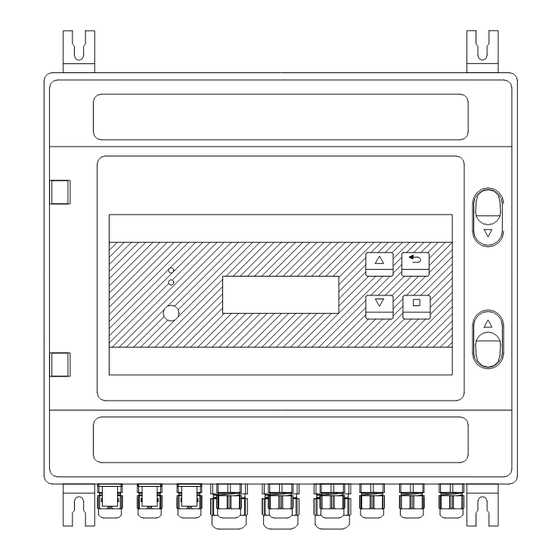
2. Installation Mount the DIGICHEM Plus+ on a flat vertical surface away from extreme heat, humidity or areas where temperature variations are extreme, ideally at eye- level to allow good visibility of the LCD display. Also ensure that a 240VAC mains power point is located nearby. - Page 7 55 56 Earth Terminals Power Terminals 19 20 21 22 23 24 25 26 27 28 29 30 31 32 33 34 35 36 Terminal Description Input Terminals Number Mains Output Active (240VAC) 37 38 39 40 41 42 43 44 45 46 47 48 49 50 51 52 53 54 Mains Output Neutral 9 10 11 12 13 14 15 16 17 18 Terminal...
-
Page 8: Conductivity Probe Installation & Maintenance
2.2 Conductivity Probe Installation & Maintenance The probe is supplied screwed into a PVC Tee piece such that the electrode tips are submerged in the water flowing through the manifold in which the tee is usually fitted. The probe should be positioned with the black markers on the probe aligned with the black markers on the manifold Tee. -
Page 9: Controller Functionality
3. Controller Functionality 3.1 Menu Logic The DIGICHEM Plus+ has an advanced but very user-friendly menu system: • The menu structure is circular • The relevant menu item, or programmed value flashes on the display, and is shown as bold letters or numbers when explained in this instruction manual. -
Page 10: Pushbuttons
3.2 Pushbuttons The DIGICHEM Plus+ has 4 pushbuttons each of which have dual functions: 1. Scroll UP (Time & Date) 2. Scroll DOWN (Main Menu) 3. ENTER (Reset) 4. BACK (View Settings) • The Scroll UP and DOWN pushbuttons allows you to scroll in both directions in the circular menus. -
Page 11: Controller Display Information
3.3 Controller Display Information Notes: (v0.91 or later) • If a pulse from a make-up water meter is received, a ‘+’ will be displayed momentarily • If a pulse from a bleed water meter is received, a ‘-’ will be displayed momentarily 3.4 Comms Port There is a Comms port on the front panel of the controller next to the LCD. -
Page 12: Start-Up
4.1 Start-Up Connect Power to the controller after installation. After a start-up sequence, the controller automatically goes into NORMAL MODE. The display should read the measured conductivity as well as the conductivity Setpoint within square brackets (which alternates with the temperature as measured by the conductivity probe). -
Page 13: Start-Up Delay
4.1.1 Start-Up Delay Main Menu > SETUP MENU > GENERAL SETUP > START-UP DELAY The Start-Up Delay feature is used to delay the operation of all control functions of the DIGICHEM Plus+ Controller upon initial power up. This could be used if it was necessary for the system water to circulate adequately, for example to sufficiently mix chemicals in the water before controlling the pH, ORP or conductivity. -
Page 14: Setting Time & Date
4.2 Setting Time & Date Main Menu > TIME & DATE NOTE: The Week Number will be automatically set 4.3 Calibration Main Menu > CALIBRATION The Calibration menu has the following displays: < M A I N M E N U > <... -
Page 15: Conductivity (Tds / Μs) Calibration
4.3.1 Conductivity (TDS / µS) Calibration Main Menu > CALIBRATION > CALIBRATE µs/TDS IMPORTANT: Select the display in either µS or TDS before proceeding. (Refer section 5.1.1) Calibrating the TDS SLOPE Main Menu > CALIBRATION > CALIBRATE µs/TDS > SLOPE CAL µS/TDS Take a sample of water from the sample valve on the manifold and measure the conductivity with a calibrated hand-held conductivity meter. - Page 16 Calibrating the µS/TDS ZERO Main Menu > CALIBRATION > ZERO CAL µS/TDS The zero is factory set so should not require calibration. However, if the display reads above zero with the conductivity probe disconnected, or with the probe dry, recalibrate the zero as follows: 1.
- Page 17 Alternative zero calibration procedure: 1. Disconnect the cable from the back of the probe. 2. Wait until the reading on the LCD is stable. If the reading does not settle to exactly 0, wait until it does not drop any further. 3.
-
Page 18: Orp Mv Calibration
< C A L I B R A T I O N > < C A L I B R A T E μ S / T D S > ► C A L I B R A T E μ S / T D S ►... - Page 19 Calibrating the ORP SLOPE Main Menu > CALIBRATION > CALIBRATE ORP > SLOPE CAL. ORP Before you proceed, set the mV simulator to the desired setting, or put the ORP sensor in the buffer solution. IMPORTANT: Wait for the measured mV reading to stabilise before proceeding.
- Page 20 Calibrating the ORP ZERO Main Menu > CALIBRATION > CALIBRATE ORP > ZERO CAL. ORP The zero is factory set so should not require calibration. However, if you want to set the zero, you will require a mV simulator with a 0mV or pH7 setting.
- Page 21 Resetting the ORP CALIBRATION Main Menu > CALIBRATION > CALIBRATE ORP > RESET ORP CAL. If you inadvertently calibrate the zero and/or slope to the incorrect values, and you cannot recover by repeating the normal calibration procedure, then you can reset the calibration and start again. <...
-
Page 22: Ph Calibration
4.3 3 pH Calibration Main Menu > CALIBRATION > CALIBRATE pH The controller should automatically detect what buffer you are using. If not, the pH sensor may be faulty, or the controller might require a calibration reset only or possibly a factory and calibration reset. NOTE: When calibrating, if the measured pH still deviates from that of the buffer after pressing ENTER, then press the ENTER... - Page 23 Main Menu > CALIBRATION > CALIBRATE pH > START CALIBRATION Follow the instructions on < C A L I B R A T I O N > < C A L I B R A T E p H > <...
-
Page 24: Testing Relay Outputs
Resetting the pH CALIBRATION Main Menu > CALIBRATION > CALIBRATE pH > RESET pH CAL. NOTE: Once a pH Reset has been done, a pH calibration will be required. < C A L I B R A T I O N > <... - Page 25 < M A I N M E N U > < T E S T O U T P U T S > ► T E S T O U T P U T S ► T e s t B l e e d [ N O ) Press to turn on...
-
Page 26: Manual Dose
When any of the Outputs are activated, the Output relay switches, applying 240Vac power onto the output terminal, which activates the pump or solenoid valve wired to it. When the Alarm Output is activated, the relay de-energises, switching the Common from the Normally Open Contact to the Normally Closed contact of the Alarm relay. - Page 27 An example of Manual Dosing the Inhibitor is shown on the following page: Page 27 of 95...
- Page 28 < M A I N M E N U > < M A N U A L D O S E > ► M A N U A L D O S E ► S e l e c t O / P [ B I O ‘...
-
Page 29: View Settings
4.6 View Settings Main Menu > VIEW SETTINGS To view all the settings you have programmed into the controller without going into the menus themselves, you can simply scroll up and down to view them all, as illustrated below: Hold <... -
Page 30: Factory Settings
4.7 Factory Settings Main Menu > FACTORY SETTINGS CAUTION: • Enter this part of the program ONLY if you wish to erase your program settings. • The default settings (listed in Section 6 of this manual) most likely will not suit your application, so it will be necessary to reprogram the controller with your desired settings. -
Page 31: Programming Setup Menu
5. Programming Setup Menu Main Menu > SETUP MENU IMPORTANT: • Once settings are changed, it is necessary to exit the SETUP MENU in order to save your settings. • Setup Menu Structure illustrated as follows: < M A I N M E N U > <... -
Page 32: Set Conductivity Units
5.1 1 Set Conductivity Units Main Menu > SETUP MENU > µS/TDS SETUP > UNITS Conductivity can be displayed in either: • TDS (Total Dissolved Solids), or • μS (Micro-siemens) NOTE: The displayed units should be selected before performing any calibration or programming of the unit. -
Page 33: Set Conductivity Hysteresis
The Bleed Setpoint is the desired conductivity value of the process (displayed in TDS or μS). When a solenoid valve is connected to the bleed output, the valve opens when the conductivity rises above the setpoint. When this occurs, the tower water is flushed to drain and fresh make-up water dilutes the system, thus lowering the conductivity of the tower water. -
Page 34: Set Conductivity Bleed Cycle
5.1.4 Set Conductivity Bleed Cycle Main Menu > SETUP MENU > µS/TDS SETUP > BLEED CYCLE When the controller calls for bleed, the solenoid valve can be programmed to bleed continuously or on a cycle until it reaches the Conductivity Setpoint. -
Page 35: Orp Setup
If you wish to have the control output continuously active during bleed (rather than cycling ON and OFF), simply set the Bleed/Pause times to 00/00s NOTES: If the conductivity is greater than 25% above the programmed setpoint, then the controller automatically adjusts the ON/OFF bleed cycle to bring it to setpoint more quickly. -
Page 36: Enable / Disable Orp Control
5.2.1 Enable / Disable ORP Control The DIGICHEM Plus+ can be programmed to have the ORP control function enabled, or disabled. See diagram below: Important: High and Low ORP alarms are disabled when ORP control is Disabled (for software versions 0.86 and older) 5.2 2 Select ORP Operation Main Menu >... -
Page 37: Set Orp Setpoint
5.2.3 Set ORP Setpoint Main Menu > SETUP MENU > ORP SETUP > CONTROL SETPOINT The ORP Setpoint is the desired ORP value of the process (displayed in mV). < O R P S E T U P > < C O N T R O L S E T P O I N T > ►... -
Page 38: Enable / Disable Ph Control
In the example above, if pH control method is set to On/Off Control, then instead of Proportional Band and Control Cycle being displayed, Hysteresis and Dose Cycle will be displayed as the last two menu options. 5.3.1 Enable / Disable pH Control Main Menu >... -
Page 39: Set Ph Setpoint
5.3.3 Set pH Setpoint Main Menu > SETUP MENU > pH SETUP > CONTROL SETPOINT The pH Setpoint is the desired pH value of the process: < p H S E T U P > < C O N T R O L S E T P O I N T > ►... -
Page 40: Setting The Control Method
With proportional control, the dosing algorithm modulates the pump based on a percentage pH variation from the Setpoint. The further the pH / ORP is from the Setpoint, the shorter the OFF period is with respect to the ON period. The closer the pH/ORP is to the Setpoint, the longer the OFF period is with respect to the ON period. - Page 41 < O R P S E T U P > < H Y S T E R E S I S > ► H Y S T E R E S I S H y s t e r e s i s : 0 5 % D O S E C Y C L E E N A B L E C O N T R O L...
- Page 42 < O R P S E T U P > < D O S E C Y C L E > ► D O S E C Y C L E D o s e / P a u s e : 0 0 / 0 0 s E N A B L E O R P C O N T R O L ? O P E R A T I O N...
-
Page 43: Proportional Control
5.4.3 Proportional Control For Proportional Control, the menu structure will be different to that of On/Off Control. For the Control Method set to Proportional Control, the menu structure is shown below for the pH setup: Note: The same cam be applied to the ORP Setup menu. Now set the Proportional Band of the Controller: Main Menu >... -
Page 44: Explanation Of Ph Control Methods
Whilst dosing, if the pH and/or ORP reading on the LCD changes very quickly, the Control Cycle will need to be as short as possible, eg 10 seconds. This will reduce overshoot, as the controller will be able to adjust its dose rate very quickly in responding to a rapidly changing pH and/or ORP. -
Page 45: Explanation Of Orp Control Methods
If dosing base, the pump will be activated when the pH drops below 7.00pH and will stop when the pH rises above 7.35 pH (ie. 7.00pH plus 0.35pH). Proportional pH Control Explanation: With proportional control, the controller will always attempt to keep the pH as close as possible to the Setpoint. - Page 46 On/Off ORP Control Explanation: If dosing oxidant, the pump will dose when the ORP readout drops below the ORP SETPOINT . Dosing will stop once the readout rises above the ORP SETPOINT plus the Hysteresis percentage. (This percentage is the Hysteresis value and is a percentage of the SETPOINT).
- Page 47 Outside of the proportional band on the opposite end, the control output is ON continuously. Proportional control, which takes place within the proportional band is explained as follows: Assuming a pump is connected to the control output, the controller will modulate the power supply to the dosing pump proportionally.
-
Page 48: Alarm Parameters
5.5 Alarm Parameters Main Menu > ALARM PARAMETERS < M A I N M E N U > < A L A R M P A R A M E T E R S > ► A L A R M P A R A M E T E R S ►... -
Page 49: Orp Level Alarms
Main Menu > ALARM PARAMETERS >µS/TDS LEVEL ALRMS < A L A R M P A R A M E T E R S > < μ S / T D S L E V E L A L R M S > ►... -
Page 50: Ph Level Alarms
Main Menu > ALARM PARAMETERS > ORP LEVEL ALARMS < A L A R M P A R A M E T E R S > < O R P L E V E L A L A R M S > ►... - Page 51 5.5.3 pH Level Alarms The High pH Alarm is activated if the pH rises above the programmed setting, and automatically resets if the pH drops below the programmed setting again. The Low pH Alarm is activated if the pH drops below the programmed setting, and automatically resets if the pH rises above the programmed setting again.
-
Page 52: No Flow Alarm
5.5.4 No Flow Alarm Main Menu > ALARM PARAMETERS > NO FLOW ALARM If the No Flow Alarm is enabled, the Alarm will activate when there is no flow detected by the optional flow switch. NOTE: A flow switch is included with all dosing systems incorporating a DIGICHEM Plus+ Controller. -
Page 53: Bleed Timer Alarm
When an alarm condition is detected, e.g. High Conductivity Alarm, the relay only trips immediately if the Trip Delay is set to 2 seconds. However, if alarms do not become immediately critical, it is better to program a delay on the alarm to prevent “nuisance trips”. If a Trip Delay, e.g. -
Page 54: Orp Dose Timer Alarm
5.5.7 ORP Dose Timer Alarm Main Menu > ALARM PARAMETERS > ORP DOSE TIMER ALM < A L A R M P A R A M E T E R S > < O R P D O S E T I M E R A L M > M a x D o s e : 1 2 0 m ►... -
Page 55: Ph Dose Timer Alarm
5.5.8 pH Dose Timer Alarm Main Menu > ALARM PARAMETERS > pH DOSE TIMER ALM < A L A R M P A R A M E T E R S > < p H D O S E T I M E R A L M > ►... -
Page 56: Timer Alarm Hysteresis (Software Ver 0.91 & Later)
5.5.9 Timer Alarm Hysteresis (Software ver 0.91 & later) Main Menu > ALARM PARAMETERS > TMR ALM HYSTERESIS < A L A R M P A R A M E T E R S > < T M R A L M H Y S T E R E S I S > ►... -
Page 57: Inhibitor & Dispersant Setup
In this case you would not want the alarms to trigger, so therefore the alarm override feature locks out, or disables all alarms for a programmable time period (0 to 99 hours). The Alarm Override is also logged as a percentage of the data logging interval in the controller’s data log. -
Page 58: Dose On Bleed Mode
< G E N E R A L S E T U P > < I N H I B I T O R S E T U P > Press ► I N H I B I T O R S E T U P M o d e : [ O n B l e e d to scroll through D I S P E R S A N T S E T U P... - Page 59 < G E N E R A L S E T U P > < I N H I B I T O R S E T U P > ► I N H I B I T O R S E T U P M o d e : [ B l e e d P u l s e s ] D I S P E R S A N T S E T U P...
- Page 60 NOTE: For most applications, it is recommended to work on a 100 second cycle. For any of the % of Time modes, you can use the table on the follow page as a guide to set your Inhibitor or Dispersant pump duty cycle: Page 60 of 95...
-
Page 61: After Bleed Mode
Dosing Pump Turn-down required ON Period OFF Period 10% of maximum dose rate 0010s 0090s 20% of maximum dose rate 0020s 0080s 30% of maximum dose rate 0030s 0070s 40% of maximum dose rate 0040s 0060s 50% of maximum dose rate 0050s 0050s 60% of maximum dose rate... -
Page 62: Twenty Four Hour Per Day (24Hr/Day) Cycle
< G E N E R A L S E T U P > < I N H I B I T O R S E T U P > < I N H I B I T O R S E T U P > ►... -
Page 63: Make-Up Water Pulses
< G E N E R A L S E T U P > < I N H I B I T O R S E T U P > < I N H I B I T O R S E T U P > ►... - Page 64 Hence, we require the pump to dose 10ml every 100 pulses counted. How long does the pump need to dose to deliver 10ml? Pump dose rate = 1300ml/hr = 0.36ml/sec Dose time = 10ml / 0.36ml/sec = 27.8 seconds (i.e. approx. 30 sec) Set PULSE COUNT = 100 Set DOSE PERIOD = 30 seconds In the example above, the pump doses for 30 seconds (i.e.
-
Page 65: Bleed Water Pulses
5.6.5 Bleed Water Pulses In this mode, the Inhibitor Pump doses proportional to pulses received from a water meter fitted in the Bleed line. The DIGICHEM Plus+ activates the pump for a set time once a pre-determined number of pulses is counted. - Page 66 After biocide dosing, bleed-off continues to be disabled for the lock-out duration, programmable from 1 minute up to 23 hours, provided the Bleed Lock-out setpoint is not exceeded. (Note: The default Bleed Lock- out Setpoint of Setpoint +20% is fully programmable, and is explained further in section 5.9).
- Page 67 The example on the following page illustrates setting up Timer Program [01] for Pump A: Note: If ORP is disabled, then Pump B will be displayed as an option. If ORP is enabled, then ORP/pH will be displayed as an option. Main Menu >...
- Page 68 < B I O C I D E T I M E R S > < B I O C I D E T I M E R S > T i m e r P r o g r a m : [ 0 1 ] S e l e c t O / P : [ N o n e...
- Page 69 The example below shows the menu structure using the previous example, where instead of Pump A, the ORP/pH Output will be activated: NOTE: For this selection, Pre-Bleed and Bleed Lockout will not appear in the menu, or the Main screen when the controller is inside or outside of an active period.
- Page 70 The Auxiliary (Aux.) output can also be switched from a timer, as per the example below: < B I O C I D E T I M E R S > < B I O C I D E T I M E R S > T i m e r P r o g r a m : [ 0 1 ] S e l e c t O / P :...
-
Page 71: Pre-Bleed Setpoint
5.8 Pre-Bleed Setpoint Main Menu > SETUP MENU > GENERAL SETUP > PRE-BLEED SETPOINT In the example above, the Pre-Bleed setpoint is set as the Normal Conductivity Setpoint less 15%. Hence, during the Pre-bleed time (ie. Immediately before biocide dosing), the normal conductivity setpoint is reduced by 15%, and the controller will try to maintain this reduced setpoint until biocide dosing commences. -
Page 72: Condenser Pump Timer
increased by 50%, and the controller will try to maintain this increased setpoint until the Lockout Period expires. By preventing bleed-off during and after biocide dosing, the system is ensured of receiving maximum benefit from the dosed biocide, as no biocide will be lost during this time via bleed-off. Furthermore, because the conductivity is reduced during Pre-Bleed, the system has a longer retention period. - Page 73 dosing, as well as for a period of time after biocide dosing. This ensures continuous water circulation and effective mixing of the biocide chemical. The time that the pump runs AFTER a biocide dose, is programmed here as the Condenser Pump Timer. IMPORTANT: If this feature is used, it is not recommended to switch the condenser pump on and off rapidly using the output test...
-
Page 74: Flow Switch
5.11 Flow Switch Main Menu > SETUP MENU > GENERAL SETUP > FLOW SWITCH With a flow switch connected to the controller, any or all of the outputs can be disabled when there is no flow. An output, when selected via this menu for flow detection, will stop immediately if no flow is detected. - Page 75 Should the flow switch be disabled altogether, please see example on the following page: Page 75 of 95...
-
Page 76: Advanced Setup Menu
< G E N E R A L S E T U P > < F L O W S W I T C H > ► F L O W S W I T C H L o g i c : [ N O R M A L ] S T A R T - U P D E L A Y I N H I B I T O R S E T U P... -
Page 77: Data Logging
< S E T U P M E N U > < A D V A N C E D S E T U P > ► A D V A N C E D S E T U P ►... - Page 78 The controller has the facility to log the following items at pre-programmed intervals: Name Description Range Example Date Date stamp of log 08/07/2008 Time Time stamp of log 12:45 Conductivity Conductivity/TDS of water 0 – 10000 1024 Temperature Temperature of water in °C 0 –...
-
Page 79: Disinfection
The pre-programmed intervals are 5, 10, 15, 30, 60, 120 or 240 minutes. If the controller is set to log every 0 minutes, then logging is disabled. Each logged entry takes up memory, so the longer the interval, the longer the time can be between downloads. - Page 80 Main Menu > SETUP MENU > ADVANCED SETUP > DISINFECTION > DISINFECT ORP SETP < D I S I N F E C T I O N > < D I S I N F E C T O R P S E T P > O R P ( m V ) S e t p t : 0 0 0 0 ►...
-
Page 81: Extra Inhibitor Dose
< D I S I N F E C T I O N > < D I S I N F E C T P R O G R A M > W e e k : ► D I S I N F E C T P R O G R A M D I S I N F E C T O R P S E T P For each week, press... -
Page 82: Water Volume Counters
< A D V A N C E D S E T U P > < X T R A I N H I B T R D O S E > ► X T R A I N H I B T R D O S E S t a r t T i m e : 0 0 : 0 0 W A T E R V O L . - Page 83 Please see the diagram below to set the Water Volume Counters: < A D V A N C E D S E T U P > < W A T E R V O L C O U N T E R S > ►...
-
Page 84: Cycles Of Concentration
5.12.5 Cycles of Concentration Main Menu > SETUP MENU > ADVANCED SETUP > CYCLES OF CONCENT. A Cycle of Concentration is the ratio between the conductivity of the cooling water system, and the conductivity of the Make-Up Water. For example if the conductivity of the cooling tower water is running at 500µS, and the Make-Up Water has a Conductivity of 250µS, the cycle of concentration is 500/250 = 2. -
Page 85: Password Setup
5.12.6 Password Setup Main Menu > SETUP MENU > ADVANCED SETUP > PASSWORD SETUP The Password Setup allows a protection feature for the DIGICHEM Plus+ Controller. The password is required to be entered twice for verification purposes. The Password feature will protect the process from any settings being changed by an un-authorised person. - Page 86 < A D V A N C E D S E T U P > < P A S S W O R D S E T U P > ► P A S S W O R D S E T U P E N A B L E ? : [ N O ] C O N T R O L L E R N A M E...
-
Page 87: Controller Name
5.12.7 Controller Name Main Menu > SETUP MENU > ADVANCED SETUP > CONTROLLER NAME A unique name can be assigned to individual DIGICHEM Plus+ units to distinguish them from other similar units in the field. Please note that the controller name is limited to 16 Characters. An example of naming a unit is shown below: 5.12.8 Site Name Main Menu >... -
Page 88: Remote Communications
5.12.9 Remote Communications Main Menu > SETUP MENU > ADVANCED SETUP > REMOTE COMS. The DIGICHEM Plus+ can communicate with a remote server via a GSM/GPRS modem, which can be supplied or retrofitted as an option. Web based software is available as a user interface to access the DIGICHEM Plus+ from any computer which has an Internet connection. -
Page 89: Lcd Contrast (Software Ver 0.80 & Later)
5.12.10 LCD Contrast (Software ver 0.80 & later) Main Menu > SETUP MENU > ADVANCED SETUP > LCD CONTRAST The LCD screen display intensity can be adjusted which will affect all text displayed on the LCD screen. The diagram below illustrates this feature: <... -
Page 90: Factory Settings
6. Factory Settings The default factory settings are outlined below. These are the settings programmed when a manual Factory Reset is initiated via the menu. Menu Setting/Item Default Start-Up Delay Count Down: 0000s (0060s for v0.91 or later) Conductivity Units TDS (i.e. -
Page 91: Specifications
7. Specifications Item Specification Power Supply 220-240VAC, 50/60Hz Power Consumption 10W max (with no loads on outputs) Inputs Conductivity Probe ORP Probe Solution Ground Probe (SS) pH Probe Flow Switch (Volt-free contact) Water meter Make-Up volt-free contact Water meter Bleed volt free contact Mains Output 240VAC continuous (4A fused) Control Outputs –... -
Page 92: Maintenance Schedule
8. Maintenance Schedule The suggested maintenance schedule provides for a guideline as to the maintenance and replacement of parts on a DIGICHEM Plus+ control system. This schedule is based on relatively clean water in a cooling tower, with no adverse conditions or phenomenon occurring. The DIGICHEM Plus+ Maintenance schedule is suggested as follows: Item: Description:... - Page 93 REMOTE COMMUNICATION OPTIONS DP-OPT-CARD-GPRS GSM/GPRS Modem card to enable full remote connectivity via the Internet (Excludes Access Fees - see options below) DP-OPT-WEB-12M Annual Fee per Controller to access the Webserver incl. e- mail & SMS costs (excludes SIM card & associated data costs) DP-OPT-WEB-SIM-V-12M Annual Fee per Controller to access the Webserver incl.
-
Page 94: Service & Technical Support
Service & Technical Support Important: Please note the serial number and product/system part number before calling for assistance. Company details Part number & Company Pty Ltd Street, Suburb, State Postcode description of controller Tel: ( ) Fax: ( ) E-mail Enclosure rating Part No: DIGICHEM-Plus+...
Need help?
Do you have a question about the DIGICHEM Plus + and is the answer not in the manual?
Questions and answers