Table of Contents
Advertisement
Quick Links
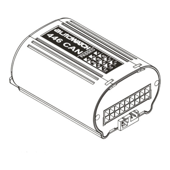
REAR VIEW OF UNIT
CAN programming connection.
Refer to programming
instructions.
LED
CAN STATUS
WIRE HARNESS INTO THE VEHICLE PRIOR
TO PLUGGING CONTROL MODULE IN
INTERNAL RELAY CONFIGURATION
+12V
UNLOCK RELAY
N.O. - GREY
N.C. - YELLOW
COMMON - BLUE
LOCK RELAY
N.O. - BROWN
N.C. - VIOLET
COMMON - GREEN
BLACK/GREY
BLACK
(UNDER CARPET SWITCH) USED FOR VALET MODE
AND ADDITIONAL FEATURES (SEE 4.0, 13.0 & 14.0)
JOIN TO THE
POSITIVE WIRE
+
+
OF INDICATOR
LIGHTS
LEFT
RIGHT
THE OUTPUT BELOW IS NEGATIVE
SWITCHING (MAXIMUM CURRENT 300mA)
WINDOWS
Requires additional Window Closer Module
(PFK Part No. 210-000)
To select this function see 4.0
& Table 1. (5.1, 5.2, 5.3 & 5.4)
Wiring information will be supplied with the Module
OR
PAGER/TRACKING
Can be connected to Pager Module/Tracking System.
To select this function see note 4.0 & Table 1 (5.1)
THESE OUTPUTS BELOW ARE NEGATIVE SWITCHING (MAXIMUM CURRENT 300mA)
SELECTIVE UNLOCKING
Refer to
To select & adjust this Function
Selective Unlocking
see Note 4.0 & Table 1
Options on Pg4
(4.1, 4.2, 4.3 & 4.4)".
& See note 1.5
OR
NEG OUT WHEN ARMED
To select this function
see Note 4.0 & Table 1 (4,4)
GP RELAY
PFK PART NO.436 900
30
87
85
Not Connected
87a
86
To one side of circuit
to be immobilised
1.
Negative Doors + Dome Light driving
2.
Can High
3.
Can Low
4.
Aux 2 (Windows/Pager) (White/Black wire)
5.
Aux 3 (Trunk release) (Black/Yellow wire)
6.
Not Used
7.
Neg. Bonnet
8.
Positive Doors
9.
Service
10.
Ground
11.
+ 12V
12.
Speaker / Siren / Horn
AUTOWATCH 446 RLC ALARM WIRING DIAGRAM
ANTENNA
Do not sleeve or tape
antenna with other wires.
Run antenna separately
and try to position
away from metallic
objects
PIN 14
PIN 15
PIN 13
PIN 23
PIN 24
PIN 22
SERVICE
PIN 9
INDICATORS
PIN 18
INDICATORS
PIN 20
See Note 11.0
& Table 1 (8,9)
WHITE/
BLACK
}
PIN 4
OR
WHITE/
BLACK
PIN
NEG
}
OUT
OR
To other side
of circuit to be
immobilised
To ignition
Connect to neg out
when armed.
13.
Unlock - Common (Blue wire)
14.
Unlock - N/O (Grey wire)
15.
Unlock - N/C (Yellow wire)
16.
Aux 1 (Selective Unlock / Neg. Out when armed)
17.
Ignition
18.
Indicators
19.
Indicator +12V
20.
Indicators
21.
Negative Boot
22.
Lock - Common (Green wire)
23.
Lock - N/O (Brown wire)
24.
Lock - N/C (Violet wire)
CAN HIGH
CAN LOW
GROUND
PIN 2
PIN 3
+ 12 VOLTS
PIN 10
PIN 11
NEG BONNET
PIN 7
SPEAKER
PIN 12
OUTPUT
INDICATOR
PIN 19
+ 12 VOLTS
+12V WHEN THE IGNITION IS
IN THE ON AND CRANK POSITION.
IGNITION
PIN 17
BOOT
PIN 21
DOORS
PIN 1
Drives interior light
See Note 10.0 & Table1 (8.3)
+ 12 V
POS DOORS
PIN 8
OR
See Note 7.0
& Table 1 (7.4)
16
TRUNK RELEASE
PIN 5
BLACK/YELLOW WIRE
TRUNK RELEASE
TO TRUNK RELEASE SOLENOID
(PFK SOLENOID PART NO. 088-510)
}
SLEEVED WITH
WIRES FROM
PIN 22, 23 & 24
}
SLEEVED WITH
WIRES FROM
PIN 13, 14 & 15
CHASSIS
CHASSIS
+ 12 VOLTS
GROMMET
BATTERY BACK UP SIREN
RED
BLACK
See Note
9.0
FUSE
+12V
IGNITION (FUSED)
NOTE : FUSES ARE
NOT SUPPLIED
DOORS
+ 12 V
Connect to
"BLUE" Door wire
RELAY REQUIRED FOR POSITIVE
WITH POSITIVE DOOR SWITCHING
DRIVER'S
INTERIOR LIGHT WILL NOT FADE
DOOR
SWITCH
G.P. RELAY Part No. 436-900
Common
+12V
Coil
+12V
Coil
INTERIOR
N.Closed
Not
LIGHT
connected
N.Open
See Note 10.0
TRUNK RELEASE
POSITIVE PULSE
To ground or +12V
Common
as required
Coil
+12V
Coil
N.Closed
Not connected
N.Open
NOT SUPPLIED - G.P. RELAY
24-WAY HARNESS
REV. 2
DPFK 695/522
01/04/09
SIREN
+ 12 V
BLACK
BONNET
+12V
Ignition
switch
BOOT
INTERIOR LIGHT
See Note 10.0
and Table1 (8.3)
INTERIOR LIGHT.
ON AND OFF
(NOT SUPPLIED)
Part No. 436-900
REAR VIEW OF
PAGE
1 OF 5
Advertisement
Table of Contents

Subscribe to Our Youtube Channel
Related Manuals for AutoWatch 446

Summary of Contents for AutoWatch 446
- Page 1 SLEEVED WITH + 12V Lock - N/O (Brown wire) WIRES FROM Speaker / Siren / Horn Lock - N/C (Violet wire) PIN 13, 14 & 15 REV. 2 PAGE AUTOWATCH 446 RLC ALARM WIRING DIAGRAM DPFK 695/522 1 OF 5 01/04/09...
- Page 2 “CANL” to the CANL or alternately to the GROUND of your vehicle in If the 446 is married to a particular vehicle, after a timed period of no CAN 1-wire CAN vehicles. Be sure to limit the length of each wire to < 30cm.
- Page 3 2 flashes 10 flashes Selective Unlock / Neg. Out when armed Neg. Out Selective 1 flash the 446 is learnt into ManufacturerID 32 & ModelID 01. Window / Pager (See 6.0) PAGER WINDOW B. If Pager is not used, the following window options may be selected: The relationship between Manufacturer &...
- Page 4 To exit NOTE : The 446 RLC has full central locking capability on board. quick test, do not trigger the alarm for a period of two minutes and the unit Connector outputs - as per diagram.
- Page 5 TO DRIVE MOTORS # +12V CONNECT TO 'REST STATE' OF MOTOR WIRES CONNECT TO SELECTIVE UNLOCK FROM ALARM (determined by the polarity of the motors at rest) REV. 2 AUTOWATCH 446 RLC ALARM WIRING DIAGRAM PAGE DPFK 695/522 01/04/09 5 OF 5...
Need help?
Do you have a question about the 446 and is the answer not in the manual?
Questions and answers
Je doi, retirer alarme de mon véhicule que je doi faire alarme défaut
Je veux retirer alarme comment de brancher et remettre le véhicule a origine