Table of Contents
Advertisement
Quick Links
Advertisement
Table of Contents

Related Manuals for Magstripe MSR400K-00

Summary of Contents for Magstripe MSR400K-00
- Page 1 TM951166...
-
Page 2: Specifications
Information ..................Technical And Operational Description .......... Connections ..................Card Data Format ................Demo Software ................. Specifications ..................FCC COMPLIANCE STATEMENT This equipment has been tested and found to comply with the limits for a Class A digital device, pursuant to Part 15 of the FCC Rules. These limits are designed to provide reasonable protection against harmful interference when the equipment is operated in a commercial environment. -
Page 3: Machine Type
MSR400 Series Magnetic Swipe Reader MACHINE TYPE FUNCTION 1 2 3 1 2 3 RS-232 BEEP MSR400R-00 1 2 3 1 2 3 KEYBOARD BEEP MSR400K-00 1 2 3 1 2 3 BEEP MSR400U-00 1 2 3 Option Function AAMVA iBUTTON 1 2 3... -
Page 4: Standard Package
Information Standard Package Main unit ( MSR400R/MSR400K/MSR400U ) Velcro Pack Software Disk WAS-1536 ( M09-P601-036 ) ( DISK5296 ) ( only for MSR400R ) ( M09-P602-036 ) Optional Power Adaptor DC5V/120VAC ( APR-1024 ) or DC5V/230VAC ( APR-1010 ) -
Page 5: Status Indicator
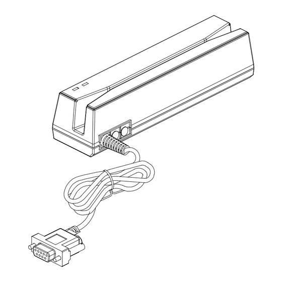
STATUS INDICATOR CARD READER USB PORT CARD READER Swipe the card through the entire length of the slot to read. ERROR INDICATOR ( Red color ) When encountering erroneous input, defective card, misread, or incorrectly encoded data, the device will turn on the ERROR indicator . READY INDICATOR ( Green color ) Indicating the reader is ready to accept new inputs. - Page 6 MSR400R DSB 9P FEMALE PIN * FUNCTION COLOR BLUE PURPLE YELLOW WHITE BLACK DC JACK...
- Page 7 connections MSR400U USB Human Interface Device (HID) Universal Serial Bus (USB) USB PIN FUNCTION COLOR BLACK GREEN WHITE...
- Page 8 connections MSR400K PS/2 MALE PIN FUNCTION COLOR PS/2 FEMALE PIN FUNCTION COLOR PC_DATA WHITE KB_DATA BLUE YELLOW YELLOW PC_CLK BLACK KB_CLK PURPLE ---- YELLOW...
- Page 9 CARD DATA STRING TRACK 1 TRACK 2 TRACK 3 TRACK1 DATA TRACK2 DATA TRACK3 DATA TRACK1 DATA TRACK2 DATA TRACK3 DATA TRACK 1 CARD ID Track 1 IATA Bits Per Inch 1. SS is the start sentinel ( % ). Bits Per Character 2.
- Page 10 Apply the bundled disk no. 5296 to begin with the demo software. STEP 1 : Run MSR Configure Cache Mode for speed up START CONFIGURE SOFTWARE STEP 2 : Choose PS/2 or COM port and press “Scan” ,connect the MSR400 reader.
-
Page 11: Demo Software
Demo Software STEP3 : Click “Read” ,scan the MSR400 reader parameter. General : Interface : MSR Interface is being detected. Buzzer : Choose buzzer enable or disable. Feed Back : Set MSR output data ,waiting for feedback from the terminal. Show `Error'message if no reaction from MSR Read the MSR parameter... - Page 12 Demo Software Keyboard : S etting MSR language ,when keyboard enable . Package : Setting MSR & iButton data output package . Data Format : MSR TK1+TK2+TK3 Data or iButton Data Checksum MSR Data Package : Prefix MSR Data Package Suffix iButton Data Package : Prefix...
- Page 13 Demo Software iButton : Set iButton data format . Data format : PS or RS Family code SS : Start Sentinel ES : End Sentinel PS : iButton present prompt character. RS : iButton Release prompt character. Present ID format : Set present iButton output ID format . Release ID format : Set release iButton output ID format .
- Page 14 TK ES0 TK ES1 Mark Code : Leading character to set up output data. Decode Mode : To decode magstripe data. Decode Standard : To decode magstripe format. 7Bit : 7 Bits Per Character data. ABA : 5 Bits Per Character data .
- Page 15 Demo Software STEP4 : Click “Write” ,write the parameter to MSR400 reader . Click “Open or Save” open or save your choose parameter to file. PS. Same as to when MSR400 reader is in RS232 interface mode, Keyboard function will be in disable mode.When MSR400 reader is in Keyboard function, RS232 interface will be in disable mode.
- Page 16 Magnetic Stripe Card : TRACK 1 / IATA / 210 bpi / 79 Alphanumeric Characters 1 2 3 TRACK 2 / ABA / 75 bpi / 40 Numeric Characters TRACK 3 / Thrift / 210 bpi / 107 Numeric Characters RS232 Interface : RS-232 RS232 , Half-Duplex , 8N1 , 1200~19200 bps...
Need help?
Do you have a question about the MSR400K-00 and is the answer not in the manual?
Questions and answers