
Related Manuals for iColor 700


Summary of Contents for iColor 700
- Page 1 Digital Label Press User Manual UniNet 3232 W. El Segundo Blvd., Hawthorne, California 90250 | sales@icolorprint.com www.icolorprint.com...
-
Page 2: Table Of Contents
Table of Contents GENERAL INFORMATION ........................4 ......................... 5 AFETY NFORMATION ........................6 YSTEM PECIFICATIONS ........................7 PECIFICATIONS 700 F ........................9 OLOR RONT 700 R ........................10 OLOR 700 I ....................11 OLOR NTERNAL EEDER 700 R ......................12... - Page 3 ........................92 OUNDING PTION ..................94 AVING AND OADING NFORMATION ......................95 OW TO EPORT 5.10 R ..........................97 EPRINT PTION 5.11 W .......................... 98 ARNING PTIONS 5.11.1 Consumable Warning ......................98 5.11.2 Fuser Warning ........................99 5.12 W ......................... 100 HITE ONER ARNING...
-
Page 4: General Information
Please ensure you follow every step in order. If your system does not comply with this list, DO NOT continue the install! Overview of the Installation System Requirements Optimal Requirement (CPU, Memory, HHD and SO) Processor: i7 3.5GHz 4770K or better Hard Drive: SSDs with 500MBs or greater Memory: 12 GB DDR3 1666MHz or greater. -
Page 5: Safety Information
1.1 Safety Information Your UniNet product has been carefully designed to give you years of safe, reliable performance. As with all electrical equipment, there are a few basic precautions you should take to avoid hurting yourself or damaging the product. Warning - Here are some of the things to look for: ... -
Page 6: System Specifications
1.2 System Specifications iColor 700: System Specifications Print Speed Up to 9.14 meters/min (30 ft/min) Technology Single Pass 4 Color LED (CMYK) Printer Processor 533 MHz Media Width Minimum: 6.0 inches (152.4 mm) Maximum: 8.5 inches (216 mm) Print Width Minimum: 6.0 inches (152.4 mm) -
Page 7: Roll Specifications
1.3 Roll Specifications... - Page 8 Packaging Notes Roll Notes 1.) Image side wound out 2.) Core: a.) Inside diameter = 3.01” – 3.025” b.) Thickness = 0.250” 3.) Core must be flush or inset < 1/16” at each end 1.) Core plugs must be used 4.) Core must be attached to the label material 2.) Roll edges must be fully supported to prevent using either double sided releasable tape or low...
-
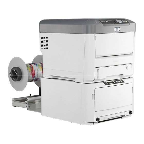
Page 9: Icolor 700 Front View
1.4 iColor 700 Front View LED Heads Toner Cartridges (C, M, Y, K) 10. Black Tray Latches Front Cover Release Lever (Blue Handle 11. Width Adjustment Wheel Behind Cover) 12. Extension Arms Cut On The Fly Module 13. Feeder Feeder Display Menu 14. -
Page 10: Icolor 700 Rear View
1.5 iColor 700 Rear View Printer Network Connection Printer Power Outlet Feeder Network Connection Feeder Power Outlet Paper Exit Path Rewinder Plate (Rewinder Not Shown Attached) Note: USB port is not available... -
Page 11: Icolor 700 Internal Feeder View
1.6 iColor 700 Internal Feeder View Drive Roller Left and Right Media Guides Tension Roller Pinch Roller Static Bar Black Tray Latches Width Adjustment Wheel Extension Arms Spindle Pin... -
Page 12: Icolor 700 Rewinder View
1.7 iColor 700 Rewinder View Left End Disk Switch Panel DC Power In Spindle Core Adjustment Knob Right End Disk Dancer Arm Lockdown Knob Width Adjustment... -
Page 13: Feeder Display Menu Functions
Feeder Display Menu Functions Display – Displays the feeder status and any error messages On Line/UP – Toggles between Online and Offline, and also serves as an “UP” selection button DOWN – Serves as an “DOWN” selection button Load Button – Press to complete loading paper Menu/Select - Accesses the three menus: Feeder Configuration, Feeder Calibration and Network Settings To access the feeder menu items, press the On Line button to toggle online or offline and gain access to your Menu system. - Page 14 This item configures the gap between back sensors. To access the I3: Reg Sensor Back menu, select the UP arrow until I3: Reg Sensor Back is shown on the display. I3: Reg Sensor To change the settings, hold down the Menu key for about one full second until the * disappears. Use the Back UP and DOWN arrow keys to set the required values.
-
Page 15: Printer Operator Panel
Printer Operator Panel ON: A warning occurs. Printing may be possible (e.g. low toner) ON: Ready to receive data BLINKING: An error occurs. 1.Ready LED BLINKING: Processing data 6. Attention LED Printing not possible (e.g. toner OFF: Offline empty) OFF: Normal Condition Displays the printer status and any 2. -
Page 16: First Time Setup
2 First Time Setup 2.1 Unpacking and Setting Up the Printer STEP 1 of 11 STEP 2 of 11 With two people lift the top (feeder) box off of the bottom (printer) box. Open the feeder box and remove the feeder. Lift the lid off of the printer box. - Page 17 STEP 5 of 11 STEP 6 of 11 Pull the drums/toners out of the printer. Remove the protective film. Place the drums and toners back into the printer. Ensure all four toners are locked into the four drums by checking the blue lever. Close the printer lid.
- Page 18 The rewinder attachment has been successfully installed. STEP 10 of 11 Once the rewinder is installed, you need to connect the network and power cables to the correct outlets. All of the outlets are located on the backside of the iColor 700; connect accordingly.
- Page 19 STEP 11 of 11 Press power button on the side of the printer. Wait for the initialization. You should read Ready To Print on the printer panel and Status: Require Load on the feeder panel. The rewinder attachment has been successfully installed.
-
Page 20: How To Get The Software Installation Files
2.2 How To Get Software Installation Files STEP 1 of 4 UniNet utilizes Dropbox for sending the software file. Please send UniNet an email for sharing folders. After this email confirmation, UniNet will send a link for the software to your email address. Click the link and you will see the above website. - Page 21 STEP 3 of 4 Go to the place to get your .zip file, right click and select Extract All. On the pop-up window, select a place to save your folder and click Extract. STEP 4 of 4 Now you have the folder for the software installation.
-
Page 22: Change User Account Control Settings
2.3 Change User Account Control Settings STEP 1 of 6 In order to prevent some administration window popping up when you use EDGE2Print, Please change your user account control setting. Click Start from Windows toolbar, and then click Control Panel. STEP 2 of 6 If using Windows 8, point your mouse to the upper-right corner of the screen, move the mouse pointer down, click Search, enter Control Panel in the search box, and then click Control Panel. - Page 23 STEP 4 of 6 Click User Accounts. STEP 5 of 6 Click Change User Account Control settings. STEP 6 of 6 Move the left bar all the way down to the bottom and click OK.
-
Page 24: Change Region Format
2.4 Change Region Format STEP 1 of 4 To prevent the confusion of measurement units display in EDGE2Print, we recommend to change region format to English (Canada). Click Start from Windows toolbar then click Control Panel. (For Windows 8, follow STEP 2 in Section 2.3.) STEP 2 of 4 Click Clock, Language, and Region. -
Page 25: How To Install Rip
2.5 How to Install RIP STEP 1 of 4 Double click the folder of 1st Re-Install RIP. NOTE: RIP must be installed before EDGE2Print. STEP 2 of 4 Click Prepare_UniNet_RIP_v2.5.exe to install. STEP 3 of 4 The KEYLOK Driver and Sentinel Driver will start to install automatically. Wait until the button turns to green. Insert your dongles and click the button to continue. - Page 26 STEP 4 of 4 Wait until the Done button turns to green. Click it to finish the installation.
-
Page 27: How To Install Edge2Print
2.6 How to Install EDGE2Print STEP 1 of 4 Double click EDGE2Print_setup.exe. STEP 2 of 4 Click Install to continue. The window will disappear after the installation is done. STEP 3 of 4 If you're using on Windows 8 and have some administration pop up window when you launch EDGE2Print software, please right click the icon, and select Properties. - Page 28 STEP 4 of 4 Click Compatibility tab, check the box before Run this program as an administrator, and click OK to apply.
-
Page 29: Setting Up The Ip Addresses
2.7 Setting up the IP Addresses In order to connect to the iColor 700, you need two predetermined static IP Addresses and two network cables, one for the printer and one for the feeder. 2.7.1 Setting up the IP Address on the Printer STEP 1 of 10 Keep the network cable unconnected to the printer. - Page 30 STEP 3 of 10 Once your IP address is correct, go to your printer panel. Press ENTER to enter the printer menu. Using DOWN arrow to scroll to Admin Setup, press ENTER. STEP 4 of 10 At the Enter Password prompt, enter the 6-digit Admin password by using the UP/DOWN arrow, then Enter. The default password is: aaaaaa(6 x a).
- Page 31 STEP 6 of 10 Hit the DOWN key until you select IPv4 Address then Enter. Use the UP/DOWN arrow keys to set the value you need. Press Enter to move across the address. After the value is set, press Back to Network Setup. STEP 7 of 10 Hit the DOWN key to select Subnet Mask.
- Page 32 STEP 9 of 10 Press ON LINE to exit the menu. NOTE: Write down this IP address as you will need for the software. STEP 10 of 10 Connect the cable to the printer and now go back to your computer cmd interface, enter "ping <IP address>" (for here is 192.168.102.222), press Enter again.
-
Page 33: Setting Up The Ip Address On The Feeder
2.7.2 Setting up the IP Address on the Feeder STEP 1 of 10 Keep the network cable unconnected to the printer. Click Start from windows toolbar (If using Windows 8, point your mouse to the upper-right corner of the screen, move the mouse pointer down, click Search), type cmd in the search dialogue and press Enter. - Page 34 STEP 4 of 10 Press Menu button three times until M3: Network Settings is shown. STEP 5 of 10 Press the UP arrow key to get I1: IP Address. STEP 6 of 10 Hold the Menu button until the * starts to flash. Use the UP and DOWN arrow keys to set the values. Press Menu button to move across the IP address.
- Page 35 STEP 7 of 10 Press the UP arrow key to set the Subnet Mask. The default subnet mask is 255.255.255.0. If that needs to be changed, follow the same procedure as for the IP Address in STEP 6. STEP 8 of 10 Press the UP arrow key to get to I3: Gateway.
- Page 36 STEP 10 of 10 Connect the cable to the feeder and now go back to your computer cmd interface, enter "ping <IP address>" (for here is 192.168.102.221), press Enter again. You should get response this time. If you're not getting reply as in the picture, please contact your IT support team.
-
Page 37: Before Printing
3 Before Printing 3.1 EDGE2Print User Interface STEP 1 of 1 This is the interface of EDGE2Print software. -
Page 38: Input Ip Addresses Into Edge2Print
3.2 Input IP Addresses into EDGE2Print STEP 1 of 2 Launch the software. This window will pop up automatically if it is the first time. Input the IP addresses for the printer and feeder, then click Save. STEP 2 of 2 If you need to change the IP address, click OptionsPrinterIP Address from the toolbar, you will get the same window as in STEP 1. - Page 39 3.3 Changing the Color Registration STEP 1 of 4 Select OptionsPrinterColor Registration from the toolbar. Go to the front panel of the printer and select the Media Type and Media Weight, based on the media settings you selected in the software library. You will want to ensure that your front panel settings and software settings are the same so you receive the exact results that are to be expected.
-
Page 40: Changing The Color Registration
STEP 3 of 4 The printer will print a similar page that will aid in determining the proper registration values across CMY. IMPORTANT: Use the third page printed to determine the values. Using a printer's loupe or best judgment, determine the best values. In this case, the correct values are as follows: C:6 M:4 Y:0;... -
Page 41: Setting Up The Cost Calculator
3.4 Setting up the Cost Calculator STEP 1 of 2 Click OptionsSoftwareCost Calculator from the toolbar. STEP 2 of 2 Input the price paid for each consumable. This will calculate the cost per label. This value will appear in the Image List. -
Page 42: Changing Units Of Measurement
3.5 Changing Units of Measurement STEP 1 of 2 Select OptionsSoftwareDisplay Options from the toolbar. STEP 2 of 2 Select your preferred measurement units to display and click Save. -
Page 43: Changing Borders On Pdf Preview
3.6 Changing Borders on PDF Preview STEP 1 of 3 Select OptionsSoftwareDisplay Options from the toolbar. STEP 2 of 3 Check the box to enable borders on PDFs display or uncheck the box to disable. STEP 3 of 3 Left one has the border enabled and right one has the border disabled. -
Page 44: Measuring Your Media
3.7 Measuring Your Media STEP 1 of 6 This is the interface of media page information in EDGE2Print software. NOTE: Gutter is the distance of the horizontal gap between labels. Alley is the distance of the vertical gap between labels. STEP 2 of 6 Measure the total width of paper. - Page 45 You also should measure the width and height of the label. Save the values for later. STEP 6 of 6 Measure the right border of the label. The distance from the edge of the facestock to the edge of the should be less than 2mm because of the sensor location on the guide.
- Page 46 Measuring Tip In order to get more precise value of gutter, there is a better way! Measure as least one meter of the media, and measure the height of one label. Then calculate the distance of the gap. The longer you measure the media, the more precise value you will get.
-
Page 47: Loading Media For Continuous Printing
3.8 Loading Media for Continuous Printing IMPORTANT: Only use with media width ranging from 6” to 8.5” wide. If use with media width less than 6", please use a narrow fuser. NOTE: Maximum Printable Width is 8.25”. STEP 1 of 13 Unpack the media, make sure the sides of the roll are straight and flush with the core. - Page 48 STEP 2 of 13 Make sure the core is thicker than 4mm. If not, when the roll is running to end, it will go out of the extension arm. STEP 3 of 13 If you 're using a die cut media, make sure the margin is less than 2mm. If you're using a back/top mark media, make sure the black mark offset from edge is less than 1mm.
- Page 49 STEP 4 of 13 Open the feeder tray by pushing the black tray latches inward and pulling the tray outwards. STEP 5 of 13 Pull out the feeder tray and open the front cover. STEP 6 of 13 Cut a small piece of the media to adjust the width of the guides. Open the left and right media guides and place the paper between the guides.
- Page 50 Remove the plastic spindle and insert it into the core of the media roll, ensuring that you keep the edges of the roll completely flush with the core. Place the roll in the feeder between the extension arms, with the leading edge of the material at the bottom of the tray.
- Page 51 STEP 9 of 13 With the media flush against the back plate in the feeder, ensure that there is no extra space on each side of the media and the left/right media guides. Feed the media underneath the drive roller and ensure that the paper is at the same level as the top of the rollers. Back wind the roll if necessary.
- Page 52 STEP 11 of 13 Power on the printer. When the feeder displays “Status: Require Load,” press the Load button on the feeder. The media will be fed upwards and cut the substrate, leaving a clean leading edge for printing. STEP 12 of 13 After the feeder cuts the paper, remove the Cut on the Fly module and scrap material.
-
Page 53: Sensor Calibration For Die-Cut Label Printing
3.9 Sensor Calibration for Die-cut Label Printing STEP 1 of 6 If your media is die cut, select Die Cut Mode. Then select the Sensor Type. (We will use the Gap Sensor as the example in the following instructions.) NOTE: If the Calibrate button is red, it means the sensor needs calibration before printing. - Page 54 STEP 4 of 6 Click Run Calibration. The printer will run the paper to the nearest gap mark. NOTE: You can use previously stored values in the feeder from the last use by clicking Copy Feeder Settings To Media Library. You can also manually input the values for Sensor Gain and Sensor Window under the Media Library Settings, and then click Copy Media Library Settings To Media Library to update the values in the feeder.
-
Page 55: Printing
4 Printing 4.1 Selecting a Media ID STEP 1 of 2 Click Media from the toolbar. STEP 2 of 2 The media list will open. It contains medias that have been certified by UniNet. You can select one from the list by double click. -
Page 56: How To Create A New Media Id
4.2 How to Create a New Media ID STEP 1 of 5 To create a new media, click the Media tab on the toolbar. STEP 2 of 5 In the pop-up window above, select the base media for your new media and right click on the Media ID. STEP 3 of 5 Fill in the Media ID, Media Description and Media Vendor, select Media Type and Media Weight from the list, then click Create This Media. - Page 57 UniNet provides a variety of substrates that have been rigorously tested for optimal print quality, ease of use and consistency from the beginning of the job until the end. The iColor 700 was designed and engineered to operate with approved consumables and certified media which ensure superior quality and resolution every time. UniNet is not responsible for damage or consequences arising from the use of non-certified media or consumables.
-
Page 58: Editing A Newly Created Media Id
4.3 Editing a Newly Created Media ID STEP 1 of 2 If the new media needs to be edited, right click on the new Media ID. STEP 2 of 2 This window will allow you to edit. After editing, click Update This Media button to update the information. If you want to delete it, click Delete This Media button. -
Page 59: Adding Label Images To Print
4.4 Adding Label Images to Print STEP 1 of 5 To open a file, choose FileOpen, or click Open File button to select your PDF file, or you can simply drag and drop your PDF file to the Preview Screen. NOTE: EDGE2Print uses PDF files only. - Page 60 STEP 3 of 5 The information of the images will show in the Image List on the left. STEP 4 of 5 Enter how many labels you want to print. EDGE2Print will automatically round the amount of labels up to complete a full row.
-
Page 61: Adjusting The Print Alignment
4.5 Adjusting the Print Alignment STEP 1 of 4 Select OptionsSoftwarePrint Alignment from the toolbar. Set the proper Pattern Header Length and Pattern Footer Length. NOTE: For every print job, you need to adjust vertically where the printer starts printing the label images. Recommendation: The header needs to be 22 inches or longer in order to adjust the color registration. - Page 62 STEP 3 of 4 Start Position Positive Value (+): Move print down Negative Value (-): Move print up STEP 4 of 4 We can also use Horizontal Shift(-/+) to make adjustment to the labels. Positive Value (+): Move print right Negative Value (-): Move print left...
-
Page 63: Nesting
4.6 Nesting Nesting is a feature where users can print multiple graphics of the same size and layout in a sequence without stopping. For example, you have three salad labels of the same size and need 10 Mediterranean, 5 Berry Blue and 25 Field Berry for one run. - Page 64 Repeat the above step until all the printing jobs are loaded. For example, we have 3 jobs loaded, Print Nesting: 3 will be displayed. Click that, and the printing process will start right away. STEP 4 of 4 If you need to edit the nesting job, click Edit button and the option window will pop up. You can add white space between nested.
-
Page 65: How To Activate Variable Data (Ivdp)
4.7 How to Activate Variable Data (iVDP) STEP 1 of 4 Select OptionsSoftwareVariable Data. STEP 2 of 4 Make sure the Dongle ID is correct and click Import. STEP 3 of 4 Open the folder that holds the Key and select Variable_Data_Enabled.dat, then select Open. STEP 4 of 4 The Variable Data tab is now on the toolbar. -
Page 66: Printing Variable Data
4.8 Printing Variable Data STEP 1 of 5 Select Variable Data from the Toolbar. The Labels to Print option now becomes unavailable. STEP 2 of 5 Open the PDF file that contains your variable data. Once loaded, click the Print button. Important: If only the first image of your variable data is visible on the preview screen, then you did not click the Variable Data tab before you load the file. - Page 67 STEP 3 of 5 Once the Print button is clicked, this window will pop up. The RIP and Separations Procession will take a while to fully process depending on your hardware. Once they have processed, their screens will turn green and a Printing Job #1 will appear.
-
Page 68: Printing Using Banner Mode
Printing Using Banner Mode STEP 1 of 5 EDGE2Print has a feature which can print a long PDF file using the banner mode. Select Banner from the toolbar. The Die Cut Mode now becomes unavailable. STEP 2 of 5 Load the PDF file into EDGE2Print. - Page 69 STEP 3 of 5 If this dialogue pops up, it means you did not click the Banner tab before you load your file. Please redo STEP 1 &2. STEP 4 of 5 If the media width is large enough to take up multiple columns of the banner, it will show in multiple columns. You can set a value to the Alley to separate each column.
- Page 70 STEP 5 of 5 You can set a value to Gutter if you want a gap between multiple banners. The output of your banner will look like the layout above. NOTE: The limitation of PDF size is 200 inches (5080 mm) long. If your graphic is larger than this, you will need to have your graphic designer create a multi-page PDF with 199 inches (5054.6 mm) sections or less.
-
Page 71: How To Activate White Toner
4.10 How to Activate White Toner EDGE2Print allows you to print white spot color and print white underneath the color for transparent media and black media. STEP 1 of 7 Install the ICC profile for using white toner first. Open the folder of Install White ICC. Double click Install White ICC.exe. STEP 2 of 7 Click the button Click to Install White ICC for EDGE! STEP 3 of 7... - Page 72 STEP 5 of 7 Click Import License. STEP 6 of 7 Open the folder that holds the Key and select White_Toner_Enabled.dat, then select Open. STEP 7 of 7 Now, click Media from the toolbar, you will see a White Toner tab with two categories Plastic and Paper.
-
Page 73: Printing Using White Toner
4.11 Printing using White Toner STEP 1 of 2 Select a media under White Toner category. You will see a "W" on the right side of the media name which indicate that the media for using white toner is selected. STEP 2 of 2 The printing process for white toner is the same as the normal one. - Page 74 Using Spot White...
-
Page 76: How To Set Up The Rewinder
4.12 How to Set Up the Rewinder STEP 1 of 6 Loosen the Core Adjustment Knob. Place a core on the Rewinder Spindle. Make sure the core is the same width of the media you’re printing on or slightly smaller. If the core is the exact same width as the media, ensure it is placed flush against the left end disk. - Page 77 STEP 3 of 6 Loosen the Lockdown Knob for positioning. When you are ready to print, send a small section of labels to the printer. While the section is printing, adjust the rewinder left/right using the Width Adjustment Knob, aligning the rewinder with the paper path as the labels exit the machine.
- Page 78 STEP 5 of 6 Press Print in the software when your job is ready. As the paper exits the printer, lift the Dancer Arm and bring the media underneath the Dancer Arm and up onto the core. Secure it to the core using a section of media or excess label.
- Page 79 When the roll is done, turn off the rewinder. Unscrew the Core Adjustment Knob on the Spindle. Remove the roll from the Spindle and return the Right End Disk to its initial position.
-
Page 80: Software Features And Options
5 Software Features and Options 5.1 How To Print a Full Bleed Die Cut Label The following is a detailed guide to create an oversized label image on top of a die cut label. The term over bleed means that there is a small portion outside of the actual label known as the “overprint area”. Excess toner of the label is printed on to this area so that the actual dimensions of the label are met with clear, clean cut edges. - Page 81 STEP 2 of 3 Input the number into proper place. For example, the label width(X) is 50.5mm, label height(Y) is 127mm, gutter is 3.175mm, alley is 3.175mm. STEP 3 of 3 If you want to print 1mm bleed outside of the label size on both direction, just minus gutter and alley by 2mm, and add 2mm to width and height.
-
Page 82: Install Your Own Icc Profile
5.2 Install Your Own ICC Profile STEP 1 of 8 When you are using the created media, you can install your own ICC profile. Click the colourful square button on the right side of your media's name. NOTE: If the media is created under white toner category, you don't have the color management option. TIP: If you have a three-column media and you want to compare three different color managements on the same sheet, you can do like this. - Page 83 STEP 3 of 8 Click Install Output ICC Profile. STEP 4 of 8 Select the ICC profile, click Open. STEP 5 of 8 Change the ICC name and ICC comment if you need, then click Save. STEP 6 of 8 Then your ICC profile appears in the list.
- Page 84 STEP 7 of 8 Notice that only CMYK ICC profile can be installed. If it is a RGB ICC profile, this window will pop up. STEP 8 of 8 After making changes, click Save to save and close the dialogue.
-
Page 85: Rip Settings
5.3 RIP Settings STEP 1 of 2 EDGE2Print has a feature to customize RIP settings for your labels if using own created media other than those under White Toner category. Click the colourful square button on the right side of your media's name. STEP 2 of 2 Click Apply ICC Profile with RIP Setup Options on the top and you will see RIP Settings on the bottom. -
Page 86: Installing The Fonts In The Rip
5.4 Installing the Fonts in the RIP STEP 1 of 9 Go to ComputerDisk(C:)Windows, double click Fonts. STEP 2 of 9 Press Ctrl+A to select all of the fonts within the folder, and press Ctrl+C to copy all of the fonts. - Page 87 STEP 3 of 9 Create a new folder in a convenient location (e.g. a folder named myFonts on the Desktop), then press Ctrl+V to paste all of the fonts into this folder. STEP 4 of 9 Open Windows Start and find UniNet RIP, click to open the software.
- Page 88 STEP 5 of 9 Click the Red Stop Light Icon to pause the program. STEP 6 of 9 Click FontsInstall Fonts from the toolbar. STEP 7 of 9 Find the new folder you just created which has all of the fonts. Double click to open.
- Page 89 STEP 8 of 9 Press Ctrl+A to select all of the fonts, and click Install. STEP 9 of 9 The fonts will start to install to the RIP. Once the job has been completed all of the fonts will be available in the EDGE2Print Software.
-
Page 90: Rip Rotate Options
5.5 Rip Rotate Options STEP 1 of 1 When the Rip Rotate Option is set to 0 all PDF files will preview in their original orientation. The Rip Rotate Options will allow for the desired orientation. For example, if you check 90 in the RIP Rotation Option, the image will rotate 90 degrees clockwise. -
Page 91: Rip Scaling Options
5.6 Rip Scaling Options STEP 1 of 1 If the size of your image is not the same as the label size, you can use the RIP Scaling Option to adjust it. Input the width of label into X(width) and put the height of label into Y(height). Select the desired scaling values, then select Clear in the Image List section. -
Page 92: Bounding Box Option
5.7 Bounding Box Option STEP 1 of 4 The software offers option to use different bounding box for your PDF file to print. First, select a user defined media, then click the colourful square. STEP 2 of 4 On the right side, you will see the Bounding Box option. Select the bounding box you want to use and click Save. The default set is MediaBox. - Page 93 STEP 4 of 4 This is the same PDF as the one above with TrimBox.
-
Page 94: Saving And Loading
5.8 Saving and Loading Page Information STEP 1 of 2 Click FileSave Page Information from the toolbar. The current page information in the software will be saved. STEP 2 of 2 To load the saved page information, click FileLoad Page Information. Select the page information file you saved before, and then click Open. -
Page 95: How To View Cost Report
How to View Cost Report From EDGE2Print toolbar click Cost Report. The Cost Report will be displayed within a text file. Notice that the 3 PDF files are in the job and each are separately calculated. The TOTAL COST of all jobs is calculated at the bottom of the page along with the TOTAL LENGTH. - Page 96 STEP 3 of 3 For variable data printing, you can select the above to generate cost report after printing.
-
Page 97: Reprint Option
5.10 Reprint Option STEP 1 of 5 Click Options->Preferences->Reprint from the toolbar. STEP 2 of 5 Check the box. This will enable the reprint option. STEP 3 of 5 If an error occurs, the error window will appear. Leave the window untouched. STEP 4 of 5 Go to your printer and feeder, correct the error, make the printer showing Ready to Print and feeder showing Status: Idle. -
Page 98: Warning Options
5.11 Warning Options 5.11.1 Consumable Warning STEP 1 of 3 Click Options->Preferences->Warnings from the toolbar. STEP 2 of 3 Check the box before Job vs Consumables will enable the warnings for running out consumables. STEP 3 of 3 For Example, after you click Print, if black toner is not enough to finish the job, the warning window will pop up. You can click OK to continue printing or click Cancel to cancel the printing job. -
Page 99: Fuser Warning
5.11.2 Fuser Warning STEP 1 of 3 Click Options->Preferences->Warnings from the toolbar. STEP 2 of 3 Check the box before Fuser Width vs Media Width will enable the warning of the fuser width according to the media width. STEP 3 of 3 For example, after you click Print, the warning window will pop up to let you know the correct size of fuser should be used according to the Media Width you input in Page Information. -
Page 100: White Toner Warning
5.12 White Toner Warning STEP 1 of 3 If you have white toner license activated, you can turn on/off the white toner warning. Click Options->Preferences->Warnings from the toolbar. STEP 2 of 3 Check the box before White Toner will enable the warning of the White toner cartridge before printing. STEP 3 of 3 If you select media for white toner, the warning to put white toner in the printer will pop up. -
Page 101: Trouble Shooting And Maintenance
6 Trouble Shooting and Maintenance 6.1 Toner Cartridge Replacement STEP 1 of 8 STEP 2 of 8 (a) Pull the colored toner release lever on the cartridge to be replaced fully towards the front of the printer. Press the cover release and open the printer’s top cover fully. - Page 102 STEP 5 of 8 STEP 6 of 8 Insert the left end of the cartridge into the top of the Remove the wrapping material and peel off the image drum unit first; pushing it against the spring on adhesive tape from the underside of the cartridge. the drum unit, then lower the right end of the cartridge down onto the image drum unit.
-
Page 103: Toner Cartridge Replacement
6.2 Image Drum Replacement The printer contains four image drums: cyan, magenta, yellow and black. CAUTION! Static sensitive devices, handle with care. STEP 1 of 8 STEP 2 of 8 Note the position of the four toner cartridges (a) and Press the cover release and open the printer’s top image drums (b) it is essential that they go back in the cover fully. - Page 104 STEP 5 of 8 STEP 6 of 8 Lift the right hand end of the toner cartridge (1) and Place the toner cartridge onto the new image drum then draw the cartridge to the right to release the left- cartridge as shown. Push the left end in first and then hand end as shown (2) and withdraw the toner lower the right end in.
-
Page 105: Replacing The Transfer Belt Unit
6.3 Replacing the Transfer Belt Unit The transfer belt unit is located under the four image drums. Switch off the printer and allow the fuser to cool for about 10 minutes before opening the cover. STEP 1 of 6 STEP 2 of 6 Note the positions of the four toner cartridges (a) and Press the cover release and open the printer’s top image drums (b) it is essential that they go back in the... - Page 106 STEP 5 of 6 STEP 6 of 6 Turn the two fasteners (a) 90˚ to the right until they lock. This will secure the belt unit into place. Replace the four image drums, complete with their toner Lower the new belt unit into place, with the lifting bar cartridges, into the printer in the same sequence as at the front and the drive gear towards the rear of the they came out.
-
Page 107: Fuser Replacement
6.4 Fuser Replacement The fuser is located inside the printer just behind the four image drum units. WARNING! If the printer has recently been powered on, some fuser components will be very hot. Handle the fuser with extreme care, holding it only by its handle, which will only be mildly warm to touch. A warning label ... - Page 108 STEP 5 of 5 Place the drums back into the printer and replace the lid.
-
Page 109: Clearing Paper Jams
6.5 Clearing Paper Jams STEP 1 of 17 STEP 2 of 17 Note the position of the four toners cartridges (a) and Press the cover release and open the top cover. image drums (b). It is essential that they go back in the same order. - Page 110 STEP 5 of 17 STEP 6 of 17 Check if any sheets of paper are visible on any part To remove sheet from the front, lift the sheet from the of the belt unit (a. release handle, b. belt, c. fuser or belt and pull it forward into the internal drum cavity to d.
- Page 111 STEP 9 of 17 STEP 10 of 17 Press release lever (g) and pull trapped paper from Replace fuser unit into the machine and move locking the fuser. levers (e) toward the rear of the machine. STEP 11 of 17 STEP 12 of 17 Starting with the cyan image drum unit nearest the Open the rear exit tray (h) and check for sheets of...
- Page 112 STEP 15 of 17 STEP 16 of 17 Pull out the paper tray and ensure all paper is stacked properly, is undamaged, and that the paper guides are Check inside the cover for sheets in this area and properly positioned against the edge of the paper remove any that you find, and then close the cover.
-
Page 113: How To Print Configuration Information From The Printer
How to Print Configuration Information from the Printer STEP 1 of 1 Press DOWN arrow, scroll to Print Information, press Enter. Select Configuration, press Enter. Select Execute. It will then start to print the page information. How to Print a Secure Job from the Printer STEP 1 of 1 Press DOWN arrow, scroll to Print Secure Job, press Enter. -
Page 114: Sensor Calibration From The Feeder (For Die Cut Labels Only)
6.8 Sensor Calibration from the Feeder (For Die Cut Labels Only) STEP 1 of 11 Follow STEP 1-7 of "Loading Media for Continuous Printing" to load the roll. Place the roll of paper into the paper tray. Feed the media through, ensuring it is underneath the tension and pinch rollers. With the media flush against the back of the machine, ensure that there is no extra space on each side of the media and the left/right media guides. - Page 115 Line up the gap of the labels about one inch below the sensor. STEP 3 of 11 Cut the excess paper to make sure the top of paper is flush with the drive roller. Backwind the roll to ensure there is no tension when the sensor is calibrating. If the roll is fully wound and has tension on it, it will skew the calibration.
- Page 116 Press the On Line button to take the feeder offline. STEP 5 of 11 Press Menu twice to get to M2: Calibrations. STEP 6 of 11 Press the UP arrow button to get to I3: Reg Sensor. Hold down the Menu button until the * disappears. Press Menu twice to get to the sensor type.
- Page 117 Press the UP arrow to scroll to I4: RSEN AutoCal and hold Menu until Ready starts flashing. Press the UP arrow to select Execute and hold Menu until it stops flashing. STEP 8 of 11 Press Menu again and it will show Status: Offline. STEP 9 of 11 Press the On Line button and the calibration test will begin.
- Page 118 After the calibration process, press the On Line button to turn the machine Offline, and then hold the DOWN button to cut the excess paper after the calibration is complete. NOTE: If you press Load at this moment, the machine might show Path Full because of the excess paper. STEP 11 of 11 Remove the paper.
-
Page 119: How To Access The Settings As An Administrator
6.9 How to Access the Settings as an Administrator You can set whether to ENABLE or DISABLE each category in the user menu. Disabled categories are not displayed in the User’s menu. Only a system administrator can change these settings. 1. -
Page 120: Paper Sensor Error Codes
6.10 Paper Sensor Error Codes Code # Location Paper Feed Upper Paper Transport Paper Exit Fuser Paper Feed Lower 10 - 11 Load Sensors Feeder Panel Error Messages: Message Issue Msg: Guide Door Open Ensure Guide Door is Closed Push Guide Tray Completely into the Feeder. Ensure Msg: Guide Tray Out Guide Tray Latches are Locked. - Page 121 Feeder Panel Errors: Error Issue Solution Emergency stop (guide door opened during Status: Error 00 Close Door on Feeder motor movement) Status: Error 01 Switch panel communication error Contact your dealer/reseller Status: Error 02 Internal error Contact your dealer/reseller Status: Error 03 Internal error Contact your dealer/reseller Media not found over lower load sensor after...
Need help?
Do you have a question about the 700 and is the answer not in the manual?
Questions and answers