Table of Contents
Advertisement
Quick Links
Advertisement
Table of Contents

Related Manuals for D16 Group REPEATER VINTAGE MODELLED DELAY


Summary of Contents for D16 Group REPEATER VINTAGE MODELLED DELAY
- Page 1 User Manual 15 November 2016...
-
Page 2: Overview
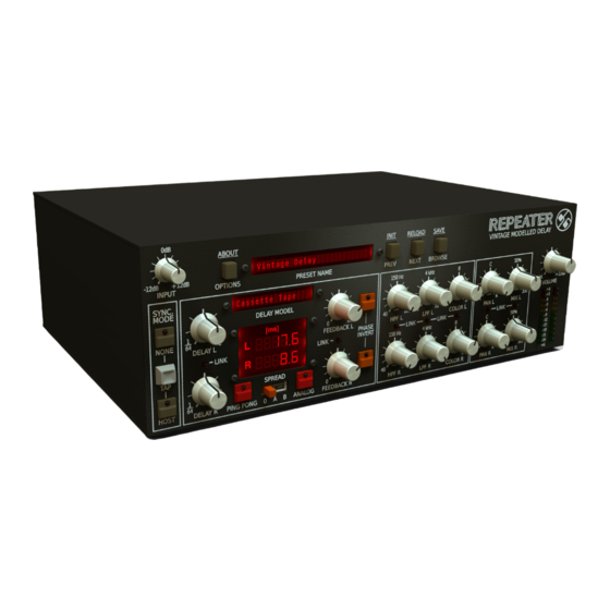
• Overview Overview Repeater is a stereo delay type effect processor with independent control of processing path for left and right channels. It also emulates the nature and of many various hardware devices of this kind (including the classic effect units). When the plug-in is loaded to the hosting application its graphic interface appears: Repeater graphical interface... - Page 3 • Overview • Configuration and Preset management section: Configuration and Preset management section • And the Signal processing section consisting of the all remaining controls. www.d16.pl...
-
Page 4: Signal Flow
PAN L • Signal FlOw INPUT COLOR L LEFT CHANNEL COLOR FLOW IN L CLIPPER Signal Flow CLIPPER IN R RIGHT COLOR CHANNEL FLOW In general, the Repeater processing path may be described as two independent paths; left and right channel. Each path has an independent COLOR R delay line and additional (identical for each channel) processing blocks, which enrich the overall capabilities. -
Page 5: Processing Blocks Before The Feedback Loop
SPREAD DELAY TIME • Signal FlOw PrOceSSing blOckS beFOre the Feedback lOOP IN R RIGHT DELAY LINE DELAY LINE CHANNEL DELAY R FLOW Processing blocks before the feedback loop FEEDBK R Preliminary amplifier and audio clipper Before the signal is fed to the feedback delay loop it is processed by the audio clipper block which results in the signal saturation which intensity depends on the gain controlled by the INPUT parameter and the ingoing signal’s amplitude. - Page 6 • Signal FlOw Preliminary amPliFier and audiO cliPPer The parameters that control this section are as follows: INPUT – Controls the input signal gain from -12 up to +12 [dB]. • Input parameter COLOR L, COLOR R – The parameters that control the tone characteristics of the left and right channel audio clipper: •...
-
Page 7: Delay Line With Feedback Loop
• Signal FlOw delay line with Feedback lOOP Delay line with feedback loop The Clipper’s output signal is fed to the delay line with feedback loop; FEEDBK L MIX L PING PONG DELAY L PAN L LEFT CHANNEL DELAY TIME FLOW IN L DRY L... -
Page 8: Delay Line Times
• Signal FlOw delay line with Feedback lOOP Repeater delay line parameter control section Delay line times DELAY L and DELAY R control (independently) the line delay times of the left and right channel from 0.1 up to 1000 [ms] (while tempo syn- chronization is disabled). -
Page 9: Tap
• Signal FlOw delay line with Feedback lOOP Delay times may also be adjusted precisely by dragging the up-down mouse pointer above the digits representing the consecutive delay decimal position on the adjacent display: Display with the current delay time for the left and right channel TAP is used to set the delay time “using ears”... -
Page 10: Synchronizing The Delay Line With The Hosting Application Tempo
• Signal FlOw delay line with Feedback lOOP This function is available only for the tempo synchronization being disabled Synchronizing the delay line with the hosting application tempo SYNC. MODE activates/deactivates the synchronization of the delay times with the hosting application tempo. Sync. - Page 11 • Signal FlOw delay line with Feedback lOOP Delay in the tempo synchronization mode DELAY L and DELAY R parameters allow to select one of the following duration values for the delay time: 1/1, 1/2, 1/4, 1/8, 1/16, 1/32, 1/64 - for the left or right channel respectively. Together with the Note Value we can select one of the three available Modifiers by clicking adequate area on the display (above).
-
Page 12: Feedback
• Signal FlOw delay line with Feedback lOOP Spread SPREAD is a left and right channel line delay time modifier. When this function is active a phase offset occurs between both delay lines, which makes an impression that the stereo scene is wider. The function operates with two intensity levels and is controlled with the SPREAD switch: Spread parameter It takes the following values:... -
Page 13: Analog Mode
• Signal FlOw delay line with Feedback lOOP Analog mode In this mode, the feedback loop works in analog-like fashion, which results in the sound becoming dimmer with each pass through the loop. Analog toggle button enables / disables this mode: Analog button Ping-Pong By default left and right channel delay line feedback loops are separated and operate independently (PING-PONG is inactive). -
Page 14: Processing Blocks After The Feedback Loop
• Signal FlOw PrOceSSing blOckS aFter the Feedback lOOP The effect is switch on/off with the toggle PING-PONG button: Ping-Pong button Processing blocks after the feedback loop This chapter describes the operation and control of the blocks processing the signal outgoing from the feedback loop delay line. Phase inverter The signal from the feedback loop is fed to the Phase inverter. -
Page 15: Dual Filter
• Signal FlOw PrOceSSing blOckS aFter the Feedback lOOP Dual filter The signal from the Phase inverter is sent to the Dual filter. This module consists of two passive filters, Low pass and High pass which operate in the cascade. They allow to remove the harmonic content outside the band specified by the cut-off frequencies of these filters: Dual filter frequency response The Repeater path includes two Dual filters, one for each stereo channel, which are controlled from the following GUI section: OUT VOLUME... -
Page 16: Stereo Mixer
• Signal FlOw PrOceSSing blOckS aFter the Feedback lOOP The parameters available here are as follows: HPF L – Left channel High pass filter cut-off frequency. Operating range from 40 up to 1000 [Hz] • LPF L – Left channel Low pass filter cut-off frequency. Operating range from 1 up to 22 [kHz] •... - Page 17 • Signal FlOw PrOceSSing blOckS aFter the Feedback lOOP The Stereo mixer block is controlled from the following GUI section: Stereo mixer section The following parameters are available: PAN L, PAN R – Re-panning the signal of the left and right channel, respectively. •...
-
Page 18: Master Section
• Signal FlOw delay line mOdelS Master section The Master section is the last Repeater processing path’s component: Master section Its parameter, OUTPUT VOLUME, is used to control the output signal gain from –inf up to +12 [dB], and the VU-meter shown below (OUT- PUT METER) indicates the current level of this signal. - Page 19 • Signal FlOw delay line mOdelS delay devices by selecting the line Model to be emulated by the plug-in. However, in spite of appearances, it does not mean that the set of available parameters or interface change. It does not mean that the set of available processing blocks and/or their interconnections change either.
- Page 20 • Signal FlOw delay line mOdelS • Digital 42 - One of the most famous modern digital delays, this one has a uniquely ‘early digital’ tone with a touch of graininess and a slight scoop. Sounds great on guitars and vocals. •...
-
Page 21: Stereo Link
• Signal FlOw StereO link The individual delay line Models directly affect such plug-in operation aspects as: • Implementation of the delay line alone - thus affecting its tone characteristics which is connected with the signal degradation, possible detune or saturation. •... - Page 22 • Signal FlOw StereO link It is possible to link up the up-down parameters in pairs so that the given parameter value is identical for both channels. You can do it with the LINK LEDs located in the middle of the interface: Link LEDs row to join the controls in pairs (left - right channel) When the connection is enabled (LED is on) the controls are interconnected and any change of the value of one of these controls automatically changes the value of other control.
-
Page 23: Preset Management
PRESET MANAGEMENT • PRESET STORAGE • BROWSING PRESETS Preset Management Preset Storage Presets, both those from the Factory content, and User ones, are stored as files in proper locations on a disc. Each time the plug-in instance is loaded to the project, these locations are scanned and presets found there are consolidated into one linear structure (list) in the Preset Browser. - Page 24 PRESET MANAGEMENT • BROWSING PRESETS SAVE – Win ( + BROWSE ), Mac ( + BROWSE ) – Saves current parameters as a new preset or allows for overwriting of • Ctrl the existing one (see sections below). BROWSE – Expands the Preset Browser panel at the bottom of GUI section. •...
-
Page 25: Resources
PRESET MANAGEMENT • BROWSING PRESETS Resources In this section you can choose a resource/resources in which you want to browse presets. There are two resources to choose from: Factory – Delivered together with the plug-in, cannot be modified (read-only). • User –... -
Page 26: Categories And Tags
PRESET MANAGEMENT • BROWSING PRESETS Categories and Tags Each preset is described by a few common Categories. Within each of them there may be one or more Tags from a particular set. CATEGORY NAME TAGS A single category in a filter with a description of its elements Presets from Factory resource were described by Categories and Tags during the stage of its creation. -
Page 27: Presets Filtering
PRESET MANAGEMENT • BROWSING PRESETS Results Section in Preset Browser Click any name to choose and load the preset. Double-click the name to enter preset name edit mode. Presets Filtering Filters section columns represent particular Categories – Category filters, while rows in each of these columns represent Tags available within each Category. -
Page 28: Basic Actions On Filters
PRESET MANAGEMENT • BROWSING PRESETS Presets Filtering with the use of Categories Tags The result of a cascade filtering process (presets that meet the criteria of each filter) is listed below, in the Results section. Basic Actions on Filters Tag buttons in Filters work in toggle mode. Click to activate/deactivate Tag (Grey color means that the Tag in inactive, teal blue means that the Tag is active). -
Page 29: Reordering Categories
PRESET MANAGEMENT • BROWSING PRESETS If you click the Tag 1-1 item again, you will deactivate the Filter, so all presets from the content will be displayed again. Reordering Categories To the right of the Category Filter header there are buttons with arrow icons: Filter reordering They enable moving the Category to the left or right in a cascade. - Page 30 PRESET MANAGEMENT • BROWSING PRESETS Edit mode button In this mode Preset Browser slightly changes its appearance (not only function): Preset Browser in Edit mode The Filters section changes into the Edit Tags section, whose appearance is almost identical, but the function is different. The section is used not as a filter, but as an editor of Categories and Tags of chosen presets.
-
Page 31: Selection Of Presets For Editing
PRESET MANAGEMENT • PRESETS EDITING – EDIT MODE Selection of Presets for Editing You can edit both single preset and a set of presets. Using the functionality of the Results section, you can choose a preset or a set of pre- sets in the following way: •... - Page 32 PRESET MANAGEMENT • BROWSING PRESETS - EDIT MODE Notification about Tags Status in Chosen Presets The change of the Tag status for one or more chosen presets sets or erases this Tag in all these presets. The status change is signalized with an Asterisk located to the left of the Tag buttons .
-
Page 33: Presets Names Editing
PRESET MANAGEMENT • PRESETS EDITING – EDIT MODE Presets Names Editing Double-click the name of a preset to enter name editing mode. Deleting Presets Selection of one or more presets activates Delete button at the bottom left corner. It can be used to delete the selected presets. Presets Export and Import The use of Import or Export buttons at the bottom part of the Preset Browser enables a proper import of presets package (exported before) or export to the presets package... -
Page 34: Saving The Current Settings As Preset
PRESET MANAGEMENT • PRESETS EDITING – EDIT MODE Saving the current settings as Preset + BROWSE ), Mac ( + BROWSE ) in Configuration To save plug-in parameters settings as a user preset use the -Win ( Ctrl and Presets Browsing section. This action automatically opens the Preset Browser with an active Edit Mode. Saving the Settings as Preset Additionally, at the bottom there will be a textbox into which you should enter a name of a newly created preset, and then confirm it by clicking Save or cancel by clicking Cancel. -
Page 35: Configuration
PRESET MANAGEMENT • SAVING THE CURRENT SETTINGS AS PRESET Configuration Parameter settings Right-click any plug-in parameter to open the context menu Closed Context Menu It allows for: • Checking the name and current value of a parameter, • Checking if the parameter is attributed to MIDI CC controller, and if it is – to which number, •... -
Page 36: Midi Learn
CONFIGURATION • PARAMETER SETTINGS MIDI Learn MIDI Learn function enables a quick assignment of physical controllers (from MIDI controller) to plug-in parameters. The assignment can be divided into a few steps: Right-click the parameter which you want to attribute to physical MIDI controller in order to expand the context menu. Click arrow at the bottom in order to expand the context menu. -
Page 37: Midi Unlink
CONFIGURATION • PARAMETER SETTINGS MIDI Unlink You can also delete MIDI CC code attributed to plug-in parameter from the context menu: 5. Open the context menu, right-clicking the parameter attributed to a particular MIDI CC 6. Expand the menu, using the arrow at the bottom 7. -
Page 38: Processing Path Quality
CONFIGURATION • PLUG-IN’S CURRENT SETTINGS Processing Path Quality Clicking the item expands the menu that allows to select the Current quality of generated sound for Real-time or Offline modes. In a case of Repeater the quality setting doesn’t affect the delay loop, but audio clipper only. Processing Path Quality Settings We can choose from four available grades for each mode. -
Page 39: Plug-In's Default Settings
CONFIGURATION • PLUG-IN’S DEFAULT SETTINGS Plug-in’s default settings The Options panel allows us to change the Default settings of the plug-in. Every time the plug-in is loaded in the host application (new instance is created) a Default settings are used for initialization of the Current settings. Default settings are stored within a configuration file of the plug-in. -
Page 40: Default Processing Path Quality
CONFIGURATION • PLUG-IN’S CURRENT SETTINGS The Options panel operates as an accordion where you can click a specific section to expand it: Options Panel There are three sections: Processing Quality - Default Processing Path Quality • Presets - Presets loading settings •... -
Page 41: Default Midi Cc Map
CONFIGURATION • PLUG-IN’S CURRENT SETTINGS Default MIDI CC Map Default MIDI Map Choice Section This section allows for setting of a path to a file with a default MIDI Map that was prepared before. Clicking MIDI CC Map check box activates load of MIDI Map and the possibility of pointing it (Browse button). -
Page 42: Table Of Contents
CONTENTS Overview ........................2 reordering categories ................29 Signal Flow ........................4 Presets Editing – Edit Mode ................29 Processing blocks before the feedback loop ...........5 Selection of Presets for Editing ..............31 Preliminary amplifier and audio clipper ............5 Tags Edition ...................... 31 delay line with feedback loop ................7 Change of Tags status in Presets ............