Advertisement
Quick Links
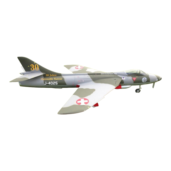
DerJet Hawker Hunter MK 58 --
Building Instruction Manual (April 2014)
Introduction
1.
Congratulations on the purchase of the Hawker Hunter, produced by DerJet Model Company, TAIWAN!
This 1/6 scale legendary jet was developed on the base of a World Masters model developed and flown by
three‐times vice champion Reto Senn of Switzerland. Thus, you did not only buy a magnificent flying plane,
this ARF kit is designed to allow participation in competitions such as the 13,5 kg class at the Jet World
Masters or others. These outlines have been originated by Flightfactory.ch GmbH on the base of the first
Hunter kits. Subsequently, minor changes/improvements in the manufacturing of the kit are not included.
(These building guidelines are in no case meant to guarantee any cover of damage or malfunction caused
by negligence, misuse, accident, unauthorized repair or modification as the final use cannot be controlled
by the manufacturer nor the author).
1/6 Scale
Advertisement

Summary of Contents for DerJet Hawker Hunter MK 58
- Page 1 DerJet Hawker Hunter MK 58 -- 1/6 Scale Building Instruction Manual (April 2014) Introduction 1. Congratulations on the purchase of the Hawker Hunter, produced by DerJet Model Company, TAIWAN! This 1/6 scale legendary jet was developed on the base of a World Masters model developed and flown by three‐times vice champion Reto Senn of Switzerland. Thus, you did not only buy a magnificent flying plane, this ARF kit is designed to allow participation in competitions such as the 13,5 kg class at the Jet World Masters or others. These outlines have been originated by Flightfactory.ch GmbH on the base of the first Hunter kits. Subsequently, minor changes/improvements in the manufacturing of the kit are not included. (These building guidelines are in no case meant to guarantee any cover of damage or malfunction caused by negligence, misuse, accident, unauthorized repair or modification as the final use cannot be controlled by the manufacturer nor the author). ...
-
Page 2: Technical Data
1/6 Scale: Wingspan: 1720mm, Length: 2340mm, Dry weight: 11,5 – 12,5 kg, Turbine: 120 – 140N thrust power, RC: 10‐12 channels (8 servos) Required equipment 3. Servos: Ailerons: use standard size servos with at least 2 x 10kg/cm torque such as Futaba BLS451 or BLS452 (MG) Elevator: use 15mm size servos with at least 2 x 5kg/cm torque such as Futaba BLS153, Graupner HBS 660 BB or Spektrum AS5030 Rudder: use standard size servo with some 10kg/cm torque such as Futaba BLS451/452, S3305/3172HV or Savöx SC‐0252MG/0254MG Flaps: use standard size servos with at least 2 x 20kg/cm torque such as Futaba BLS155/175HV or Savöx SH‐1256TG RC power supply: We recommend using a dual power supply system such as PowerBox Systems In the first three Hunters, we used once PowerBox Evolution (with external door sequencer) and for convenience, twice PowerBox Cockpit SRS (with integrated door sequencer and dual satellite reception) powered by LiPo 7,4V with 2 x 2800mAh capacity or LiFe 6,6V and 2 x 3200mAh capacity. Turbine: The light and yet solid construction of the DerJet Model Hunter allows for a wide range of turbines. Flying with with 12‐14N of thrust power is sufficient for flight performance. Yet, it allows safe take‐offs from every surface at the cost of slightly higher speed in the final landing approach. The use of a JetCat P90RXi (10,5kg thrust) by one Swiss pilot allowed both comfortable take‐offs (40m on hard surface runway) and smooth realistic flying with reasonably short landings. ... -
Page 3: Optional Accessories
Optional accessories: To upgrade your DerJet Model Hawker Hunter to a full‐scale jet, the optional parts are highly recommended both for static and flight display including underwing tanks and detailed kit of cannon blast deflector, antenna. Main wing completion 5. Building the wings is straight forward and does not take much time. If you do both wings at the same time, just make sure that one pair of servos is opposite handed as shown in the pictures. Start with the installation of the servos, which fit perfectly into the factory‐installed servo mounts. ... - Page 4 Just use the servo grommets and the servo cover will keep the servo well fixed and in place. Watch out for the servo lead to move free and prevent it from being scratched by sharp fibre edges. Should you wish to install functional position lights, you have to drill a hole of 4mm from the light location towards the aileron servo mount through wooden formers. I glued a 4mm drill into an aluminium tube 5x4mm to allow drilling to the distance. Once drilled, pre‐install the light wires or finish installation of the lights before mounting the aileron servo. ...
- Page 5 Run the servo and light wires with the factory‐installed white line towards the inner side of the wing and do the same with the flap servo. Make sure the neutral position of the servo horn is correct before finally positioning the two servos. Start now with the flap and draw the position of the three flap hinges from the wing to the flap. ...
- Page 6 Carefully drill a 5mm hole into the flaps, starting with smaller drills and smartly increasing the diameter. Rougher methods might result into damaged surface of the painted flap. Repeat this drilling to open the holes for the hinges on the wing, positioning the hole as far away as possible from the flap to allow free movement. ...
- Page 7 ...
- Page 8 Glue the three hinges into the flap after having controlled easy and smooth travel, using a 24hrs glue such as UHU Endfest 300 and thickening material such as thixotropic powder. You may want to shorten the hinges to fit the holes on either side of the flaps and wing as shown in the picture. Add one tiny drop of oil into the hinge point to avoid being glued together. Make sure the oil does not spill over the hinge where it should be glued! Once dry, glue the other side of the hinges into the wing, using the same glue and fix it well during the drying process. ...
- Page 9 Once dry, mark the positions for the control horns for both the aileron and flap using masking tape. ...
- Page 10 Place the control horn for the aileron such as the pilot hole is right over the moving line of the flex‐strap of the aileron, allowing the servo to travel at the same force up and down. The flap control horn can be installed slightly to the rear edge of the wing, allowing larger travel and thus more leveraged force from the flap servo. Carefully open now the required slot lengths for the control horns using a dremel cutting disc or other tools you are familiar with. ...
- Page 11 Now drill a 3mm hole (or smaller if using a clevis) into the horns and roughen the lower part where they will be glued into the control surface. Apply sufficient amount of glue into the slots as well as on the horns for perfectly solid fit. Fix the control horns during drying. Once the glue has fully cured, install the pushrods and re‐mount the servo hatch covers such as the servo horns can move free into the cover slots. ...
- Page 12 ...
- Page 13 It is recommended to mount the main landing gear and its doors in two steps. As the mechanics and legs as well as the wheels are factory‐assembled, the first step is done quickly. Before screwing the mechanics in place, fix the 3mm‐tubes (two different colors of your choice from the hardware pack) over the small fittings. Run the tubes into the wing and smoothly back through the holes in the wooden formers and make sure they move freely and do not bend. Leave enough length so far and cut it later to your preferred length. Install now the mechanics with either wood screws or with M4 screws and self‐tapping nuts underneath the wooden supports. Both have been tested in practice and the simple wood screws sustain well even on rough surfaces. Track now the wheel angle temporarily until you are done with the final assembly and do a roll‐out. ...
- Page 14 Mark the position of the screw holes over the main gear doors using the masking tape. ...
-
Page 15: Horizontal Stabilizer Assembly
Horizontal stabilizer assembly 6. As for the main wings, finishing the stab is even easier to do as they come with factory‐installed servo mounts as well as the elevator fixed with flex‐strips. That leaves you with the choice of servos to install and gluing the control horns. This has been explained in the main wing section which you may simply “copy and paste” this for the stab. The design of the servo mounts leaves a wide range of suitable servos at your discretion. The Futaba BLS153 should provide high security and enough power. We recommend to choose servos with at least approx. 5kg/cm of torque and preferably metal gears. I used a double‐sided foamy tape to cover the servo side and touching the hatch cover, which additionally holds the servo in place once the cover is firmly screwed in place. ... - Page 16 ...
- Page 17 ...
- Page 18 ...
- Page 19 So simply assemble the two stabs with the included solid carbon stabs and just drill a small 2mm hole in each of the lower side parts of the stabs and use a 2,2mm self‐tapping screw to hold them in place. ...
-
Page 20: Rudder Assembly
Rudder assembly 7. The kit again leaves you with the choice of installing servo horn, pushrod and control horn outside such as for the ailerons and elevators, which is straight forward. As the vertical fin provides sufficient space to mount a standard sized servo and let the pushrod run inside, it may increase your appetite for a more scale‐like solution with barely seeing any mechanics. In any case, the rudder is fixed with two hinges. Well glued, they have proved enough strength to resist any rudder force. I recommend to first glue the hinges into the rudder. When placing them into the existing holes, watch the hinge points to be in line and as far in so you bend at a 90° angle and again parallel to each other. ... - Page 21 With our scale solution, you need to make a new 5mm hole on rudder and fin for the hinge slightly up where we let run our pushrod inside the fin. Once well cured and BEFORE you glue the rudder to the fin, you would have to install the control horn for our “full‐scale” solution. Adjust the horn on your preferred side and let just enough room or length to easily to install a clevis later from the pushrod. Pre‐install the rudder without gluing it to check for free movement. Putting the rudder in place may be tricky and I found the easiest way is to enter from 90° and slightly from upwards. Once the position is found to be correct, apply again 24hrs glue (I use UHU Endfest 300) with thixotropic powder and do not forget to put a tiny drop of oil onto the hinge point. Fix the rudder well in place and in line with the fin. Install now the rudder servo into the preformed bay and I also used a double‐sided foamy tape to cover the servo side and touching the hatch cover, which additionally holds the servo in place once the cover is firmly screwed in place. ...
- Page 22 Installation of the speed brake 8. The first step is to carefully drill two 3mm holes into the moulded horns. I glued a 3mm drill into a brass tube with 3mm inner diameter using CA. With this self‐made tool, it is easier to drill as shallow as possible. Watch out to not drilling too low as you won’t be able to mount the ball coupling from the large cylinder included in the kit. Do not drill too high either as you risk to thin the control horns out which could result in a break during use in flight. ...
- Page 23 To drill a hole of about 7‐8mm into the edge of foreseen place to fix the speed brake cylinder with its wooden support included in the kit. Also to drill two holes and run the air tubes into the hole and make sure they are sufficiently in length to reach your valve system at your choice. Glue the support with at least 30min epoxy and have it well centered and fixed in place while curing. To fix the speed brake in the inside of the rear fuselage. Moreover, you can made a small support from a piece of wood and run a 2mm steel rod inside a plastic tube over the wood from left‐overs. This simple construction does its job well so far. ...
- Page 24 That’is it! The speed brake looks fantastic in the air. ...
- Page 25 Thrust tube mounting 9. Installing the thrust tube is your final step in the rear fuselage assembly. Should you have installed a light system (position lights) into the main wing, you may want to place an ACL light (white) into the rear end of the fin body. Just carefully remove the transparent cover at the end using a sharp knife, drill a hole and fix your light (and test it...) before again gluing the cover cone with some silicone glue. Before finally fixing the thrust tube, make sure all your wires are well run through the fuselage towards the front part and well protected against any heat from the tube. ...
- Page 26 Now place the tube such as it ends 5 to 10mm before the rear edge of the fuselage to allow correct positioning of the turbine. Depending on the turbine and tube cone you want to use, temporarily hold the tube in place. The cone included in the kit works well for all turbines, particularly for the smaller diameters and thus lighter engines such as a JetCat P100RX. We did choose to use a larger cone from JetCat for both the P90RXi and P140RX as it allowed us to move the turbine forward towards the CG. In any case, check out the thrust axis now and make sure that everything is aligned and well centered from looking into the tube from the rear. At this point, chose to either finally fix the tube with two screws to the front former of the rear fuselage or to skip to step 11, the turbine installation. ...
- Page 27 Front landing gear/doors installation 10. Start with fixing the steering servo (we use a Futaba S3305MG or similar with about 10kg/cm of torque and, importantly, metal gears) with the included screws onto the front landing gear (FLG) and adjust the pushrods, check neutral signal of servo before re‐screwing the servo control arm on the servo. Depending on the control arm, you will have to cut the area of the opening for the FLG. Take care not to cut too deep toward the fuselage. Before installing the mechanics, again mount the two air tubes onto the FLG cylinder. When finally screwing the FLG at its place, use a drop of thread‐lock on each of the screws running into the self‐tapping nuts. Prepare now the front door to be fixed with a flap hinge. To grind the grooves for the hinge as shown, ...
- Page 28 The air cylinder is attached to the ear of front door and fixed to its wooden support. ...
- Page 29 To glue the wooden support of air cylinder to F1 plywood, allowing the full opening of the front door. In any case, you have to take care of the front wheel running extremely close to the door and hinge. You will probably have to trim the hinge and make it as slim as possible. We later upgraded here and used an aluminum hinge. Prepare the rear door to be fixed with a live hinge, allowing a backward door opening. You can place a fiberglass cloth or an alternative which is glued tightly inside fuselage by applying 5min epoxy. ...
- Page 30 You almost got it – just connect between the FLG and ears of the rear door with two pushrods in correct lengths. Check out that your screws to the leg do not fix the moving support ring onto the leg, but only secure the pushrods (use thread‐lock) to it. ...
- Page 31 Installing the inner doors of the main gear is again not difficult at all. To grind the grooves over the doors and create shaped holes for the hinges as shown, ...
- Page 32 After installing the door with air cylinder attached, you need to drill the holes for the hinges from inside and screwed on from outside. ...
- Page 33 After drilling two holes for air tubes, the mounting of the air cylinder is quite tricky as you need to watch out for the correct travel length, allowing full opening of the inner doors. When gluing the wooden support in a proper position, you might need to grind the wood in a curved shape to be fitted. ...
- Page 34 ...
-
Page 35: Fuel Tank System
Fuel tank system 11. The ARF kit comes with two main fuel tanks and a hopper tank including all hardware needed. The design is simply highest engineering art and they fit perfectly into our cigar‐shaped fuselage. The system is intended to give you utmost freedom in how to use them. Each tank offers approximately 2,2 liters of fuel capacity. In total and counting the included UAT, you have a sound 4,7 liters – great for flying schools who can safely make long or multiple flights. Should you decide to add a smoke system, just use one tank for fuel and the other for smoke oil. If you prefer flying at light weight, use only one tank together preferably with a slightly larger UAT . On the last kits, we targeted to move the turbine as far forward as possible and thus the tanks had to be shortened. I did cut approximately 70mm from the original length and fit them again together, using glass fiber bands and 24hrs resin. After completion of this “surgery”, it is imminent to check the tanks for leakages. Best to attach your air compressor and push them, carefully filled with some air (there is no need to test them at 10 bar!) under water, leaks will immediately been seen as small bubbles appear! ... - Page 36 Finish your fuel system with the included hardware (the photo shows a similar system as preferred by the customer/owner). Make sure in any case you choose to configure your fuel system, the clunks in the main tank(s) moves freely in any position and if you are using an UAT, do not install felt clunks into the main tank(s) as this will sooner or later kill your fuel pump due to excessive vacuum built‐in. ...
-
Page 37: Turbine Installation
Turbine installation 12. The ARF kit foresees a non‐bypass installation of the turbine. If you use a JetCat or similar engine with offsetting mounts, you will have to raise the turbine by about 10mm, using a piece of plywood to be glued onto the ply mounts included in the kit. Depending on the choice of cone and final length of your thrust tube, place the turbine temporarily, respecting the gap between the rear of the engine’s exhaust and the front edge of the cone of the tailpipe according to specifications given by the turbine manufacturer. Glue the ply spacers with white wooden glue (Ponal Express) to the ply mounts. Once cured, drill 4mm holes using the turbine mount as a tool. Make sure the turbine mount is well centered and aligned. Use self‐tapping screws to mount the turbine. Install a jet‐net prior to installing the turbine to protect your engine from herbs, dust and others. Now check again the centreline of turbine and thrust tube to guarantee a long‐life at reasonable temperatures in the rear part around the thrust tube. You are done with most of the work! ... - Page 38 ...
- Page 39 RC and turbine equipment installation 13. This section is probably the most individual work to be done and mainly at your own discretion. From our experience with the first Hunters in the air, I recommend installing all more or less heavy equipment as far forward as possible, given the slim shape of the fuselage and thus limited space available. My turbine battery (I use a PowerBox LiPo 7,4V 4000mAh) is placed just above the FLG and the two receiver packs (PowerBox LiPo 7,4V 2800mAh) are screwed to small wooden supports and glued to either side underneath the front cockpit shield. An example layout is shown for most of the other components used in one of our Hunters. If you intend to install a cockpit, check out for the height of your equipment plate. Additionally, the PowerBox switch should be mounted somewhere underneath the two covers over tanks and turbine as this provides easy access later on the field. ...
- Page 40 ...
-
Page 41: Final Assembly
Final assembly 14. Before going to the air field for a first roll‐out and maiden flight, take your time and run through all parts again. You may want to ask an experienced modeler giving a second opinion and fresh view on certain installations, questioning some points that may detect an unsafe solution. Also make sure that both your air and fuel system have been filled and proven absolutely leak‐free. Start the turbine and let it run for some minutes, just to be sure no leaking fuel fitting forces the engine to flame‐out after take‐off, resulting in a worst case on your maiden flight! Check out the values on the turbine’s control unit for at least temperature, RPM’s and fuel pump voltage. The center of gravity (CG) of your Hunter should be between 280‐290mm from the rear edge of the main wing, preferably at 290mm for the maiden flight and measured with empty main tanks (UAT filled) and landing gear extended. The use of nose weight will be required to attain the proper center of gravity (CG). ... - Page 42 The following control throws have been recommended to provide scale type flight handling: Aileron: 18‐20mm each way (use 50‐60% exponential function if desired) Elevator: 15mm each way (use 50% exponential function if desired) Rudder: 25mm each way Flaps: 40mm for take‐off, 100mm for landing We wish you plenty of enjoyable and safe flights with your DerJet Hunter! ...
Need help?
Do you have a question about the Hawker Hunter MK 58 and is the answer not in the manual?
Questions and answers