
Related Manuals for Kingspan FPW18


Summary of Contents for Kingspan FPW18
- Page 1 Solar Thermal Energy FPW FLAT PLATE INSTALLATION MANUAL T: +44 (0) 28 3836 4520 www.kingspanthermomax.com...
-
Page 2: Table Of Contents
Contents Introduction Using this guide Technical Specifications Construction of Collector Mounting the Panel A-Frame On-roof Bracket Kit On-roof Bolt Kit In-roof cassette dimensions In-roof cassette mounting Connection Information Connection guidance Pipework 1st fix Standard pipework connections Dual Collector Installation Pump Station Safety Vessel Connections Wiring the Solar Control Panel Maintenance... -
Page 3: Introduction
For large systems, Kingspan provides a system design service to technical design consultants. This guide will illustrate and explain how a system should be installed to conform with the Kingspan Environmental manufacturer guidelines for the Solar Thermal product models, namely DF400, HP400, Varisol and FPW. -
Page 4: Technical Specifications
FPW Collector Installation Manual Technical Specifications Specification / Type FPW18 FPW21 FPW25 Dimensions (mm) 1929 x 933 x 91 1988 x 1041 x 90 1990 x 1222 x 91 Casing Material Electrostatically Painted (Black) Aluminium Case Weight (kg) 37.2 Sealing Material EPDM &... -
Page 5: Construction Of Collector
Construction of Collector The glass is sealed in the collector frame with EPDM and rubber. EPDM is used for sealing and it is resistant to 150˚C and the aging effect of the sun. Silicone is applied between the EPDM and glass. -
Page 6: Mounting The Panel
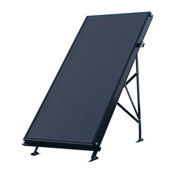
FPW Collector Installation Manual Mounting the Panel: Flat Roof A-Frame Kit FPW18 SINGLE: KFP0024 FPW18 DOUBLE: KFP0025 FPW21 SINGLE: KFP0014 FPW21 DOUBLE: KFP0015 FPW25 SINGLE: KFP0049 FPW25 DOUBLE: KFP0050... -
Page 7: On-Roof Bracket Kit
Mounting the Panel: Flat Roof On-roof Bracket Kit FPW18 SINGLE: KFP0026 FPW18 DOUBLE: KFP0069 FPW21 SINGLE: KFP0016 FPW21 DOUBLE: KFP0068 FPW25 SINGLE: KFP0072 FPW25 DOUBLE: KFP0073... -
Page 8: On-Roof Bolt Kit
FPW Collector Installation Manual Mounting the Panel: Flat Roof On-roof Bolt Kit FPW18 SINGLE: KFP0215 FPW18 DOUBLE: KFP0201 FPW21 SINGLE: KFP0202 FPW21 DOUBLE: KFP0203 FPW25 SINGLE: KFP0204 FPW25 DOUBLE: KFP0205... -
Page 9: In-Roof Cassette Dimensions
Before mounting the cassettes, please check the dimensions above. Add the dimensions of the cassettes to the collector dimensions using the table below. Individual Collector Dimensions Length (mm) Width (mm) FPW18 1929 FPW21 1988 1041 FPW25 1990... -
Page 10: In-Roof Cassette Mounting
FPW Collector Installation Manual FPW In-roof Cassette Mounting Instructions >= 21° Usable from 21° roof pitch Version2/10012013 Art-Nr. +30450 1 = Left frontpart pan tiles 9 = supporting plate 2 = centre frontpart pan tiles 10 = left backpart 3 = Right frontpart pan tiles 11 = centre backpart 4 = Single fixation bracket 12 = right backpart... - Page 11 In-roof Mounting For the fixation of the frontparts, place additional roof battens as shown in pict. no. 2. > 40 If the tiles are higher than 40 mm, cut them on the upper side as shown in the picture. Start the mounting with the left frontpart.
- Page 12 FPW Collector Installation Manual In-roof Mounting Place the center frontpart on the roof batten like the left one and plug it together with the left frontpart until it fits to the marked line on the left frontpart (pict. 6). Then fix it with 4 sealing screws (pict.
- Page 13 In-roof Mounting Place the right frontpart on the roof batten like the left and center one and plug it together with the center (left in the case of only 2 collectors) frontpart until it fits to the marked line on the center (left) frontpart (pict.
- Page 14 FPW Collector Installation Manual In-roof Mounting After the frontparts are mounted, the next step is to place the collectors (pict. 10-12). For details of the pipe connections, see pages 30-32...
- Page 15 In-roof Mounting Fix the left collector on the outer side with a single fixation bracket on EVERY roofbatten! Place a double fixation bracket on EVERY roof batten between the collectors. Place a single fixation bracket on EVERY roof batten on the outer side of the last collector.
- Page 16 FPW Collector Installation Manual In-roof Mounting Fit the left sidepart to the collector as shown in pict. 17 and 17a. Place a 100 mm foam gasket as shown in pict. 18 and 19...
- Page 17 In-roof Mounting Bend the flaps on the left sidepart as shown in pict. 20-21...
- Page 18 FPW Collector Installation Manual In-roof Mounting Fix the bent flaps with 2 rivets. Bend the flap on the left frontpart over the left sidepart. Fix the left sidepart with a fixation clip and a nail on EVERY roof batten.
- Page 19 In-roof Mounting Mount the right sidepart following the same procedure as for the left (pict. 16-24). Place the connection parts as shown in pict. 26, 27 and 27a.
- Page 20 FPW Collector Installation Manual In-roof Mounting Place a 100 mm foam gasket as shown in pict. 28 and 29 Bend the flaps on the lower side of the connection part shown in pict. 30 and 31.
- Page 21 In-roof Mounting Fix the bent flaps with 2 rivets.
- Page 22 FPW Collector Installation Manual In-roof Mounting For the fixation of the supporting plates and the backparts, place additional roof battens as shown in pict. no. 34 and 35. Place the supporting plates as shown in pict. 36, 37 and 37a.
- Page 23 In-roof Mounting Fix every supporting plate with 2 nails on the roof batten. Bend the flap on the upper side of the connection part along the perforation that it fits to the hole on the supporting plate (pict. 39 a).
- Page 24 FPW Collector Installation Manual In-roof Mounting Fit the left backpart to the collector and into the left sidepart. (Pict. 41 and 42).
- Page 25 In-roof Mounting Fix the left backpart with 2 sealing screws on the roof batten. Fit the center backpart to the collectors profile as shown in pict. 42. In the case of only 2 collectors please continue with the right backpart (pict. 46). Fix the center backpart with 2 sealing screws on the roof batten.
- Page 26 FPW Collector Installation Manual In-roof Mounting Fit the right backpart to the collector and into the right sidepart. (Pict. 47 and 42). Fix the right backpart with 2 sealing screws on the roof batten. Place the backpart connection as shown in pict.
- Page 27 In-roof Mounting Place the backpart connection as shown in pict. 50 so that the holes fit to the holes in the supporting plate. Then fix the backpart connection with 1 pcs. sealing screw on the roof batten and 3 pcs. M5 sealing screws through the windings in the supporting...
- Page 28 FPW Collector Installation Manual In-roof Mounting Fix the left and the right backpart with 2 fixation clips and nails on the roof 4,5 mm batten and with 1 rivet (pict. 52 and 53). ø 4,5 mm ø Form the left and the right frontpart at the corners to the conture of the roof tiles.
- Page 29 In-roof Mounting Place foam gaskets around the sideparts and the backparts as shown in pict. 55 Foam gaskets are only needed for pan-tile cassettes. Finally form the aluminium apron to the contures of the roof tiles as shown in pict. 56 and fix it with the adhesive strip (only for pan tiles).
- Page 30 FPW Collector Installation Manual In-roof Mounting Left frontpart pan tiles Supporting plate Center frontpart pan tiles Left backpart Right frontpart pan tiles Center backpart Single fixation bracket Right backpart Double fixation bracket Backpart connection left sidepart Left frontpart flat tiles right sidepart Center frontpart flat tiles...
- Page 31 Types of Connections The only pipes which should be used with a solar installation are copper pipe, continuous flexible stainless steel or mild steel. When using copper pipe, only compression or brazed joints can be used. Solder and galvanised fittings will not withstand high temperature or expansion and are therefore not suitable for solar pipe work.
-
Page 32: Pipework 1St Fix
FPW Collector Installation Manual Connecting 1st fix part number KSK0032 1. ISO228R 3/4” to G 3/4” 4. 3/4” stop ends 2. 3/4” washers 6. PT1000 sensor 3. DN16 hose 2m preassembled 11. Sensor retaining cap... -
Page 33: Standard Pipework Connections
Flat Plate Connection Kit - KFP0067 1. ISO228R 3/4” to G 3/4” 2. 3/4” washers 3. Stop end... -
Page 34: Dual Collector Installation
For larger scale systems up to 8 panels can be connected in series by the method described above. For design of larger scale solar system please contact Kingspan Thermomax. -
Page 35: Pump Station
Pump Station The Kingspan Environmental Solar Thermal product range offers both a single stream and a dual stream pump station. The maximum flow rate required on a system is typically 1 litre per minute, per square metre installed for systems up to 12m... -
Page 36: Safety Vessel Connections
FPW Collector Installation Manual Safety Vessel Connections Pressure Relief Valve (PRV) Rated at 6 bar, the PRV may discharge heat transfer fluid (Solar Antifreeze Fluid) which must be channelled into a container capable of withstanding high temperature discharge and containing the total collector volume. -
Page 37: Wiring The Solar Control Panel
Wiring the Solar Control Panel All electrical aspects of the installation should be undertaken by a competent person. Note that for safety, the pump and sensor connections should always be wired prior to connecting power to the solar control panel. IMPORTANT: The solar control panel must have a permanent electrical power supply which must not be interrupted either manually or with a time switch. - Page 38 FPW Collector Installation Manual Wiring the Solar Control Panel Wiring layout for SC400 and SC500 only Power connection terminal block L: 1x phase conductor (mains input) R1, R2: 2x output (TRIAC, for pumps or valves) X: not used Lconst.: 2x phase conductor (outputs, permanent voltage) N: 4x neutral conductor (common neutral conductors for mains power input and outputs) Note: Outputs R1 and R2 are protected by an electronic fuse.
-
Page 39: Commissioning The System
Commissioning the System System Pressure The recommended system pressure is 1 bar + 0.1bar/ 1m static height. Expansion Vessel IMPORTANT: On systems up to 12m Collector area, prior to filling the system, the expansion vessel pressure must be set 0.3 Bar below the system pressure. Omitting to perform this check will result in irregular pressure readings during the commissioning of the system. -
Page 40: Disposal Of Solar Antifreeze Fluid
FPW Collector Installation Manual Setting the flow rate The pump may only be run when the system has been filled as dry operation will damage the pump. The desired maximum flow rate for systems up to 12m Collector area is 1 litre per minute per m 1. -
Page 41: Servicing And Maintenance
This should be done by the installer or a heating engineer certified to work on solar thermal systems. Kingspan Environmental Services have a team of highly experienced and qualified service engineers that are equipped to carry out all the necessary checks. Call our team to arrange... - Page 43 Important Guidance for UK and Northern Ireland (NI) In order to comply with the new MCS012 requirements in the UK and NI, MCS012 compliant kits should be used. For more info contact us on +44 (0) 28 3836 4520 or email solar@kingspan.com.
-
Page 44: Decommissioning The System
Remove panel interconnections (2 or more panels) ❱ Remove panels and separate materials. ❱ Disposal Dispose of separate materials in accordance with local regulations. Please see ‘Construction of Collector’ section for details of materials used in the construction of Kingspan collectors. -
Page 45: Warranty Statement
Contract shall not exceed the Price of the Goods. 9. Kingspan Environmental shall not be liable to the Buyer or be deemed to be in breach of the contract by reason of any delay in performing or any failure to perform any of the Company's obligations in relation to the Goods if the delay or failure was due to any cause beyond the Company's reasonable control. - Page 48 Kingspan Environmental Ltd 180 Gilford Road Portadown | Co. Armagh BT63 5LF United Kingdom Tel.: +44 (0) 28 3836 4520 solar@kingspan.com www.kingspanthermomax.com Due to our continuing policy of development and improvement we reserve the right to alter and amend the specification as shown in this literature.
Need help?
Do you have a question about the FPW18 and is the answer not in the manual?
Questions and answers